Page 20 Installation and Operating Guide English
Installation and Operating Guide pro.Bose.com
Setup and Configuration
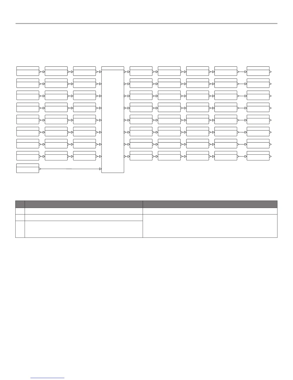
Figure 8 shows the basic signal flow and available DSP functions available to manipulate each individual input channel.
Some functions and advanced parameters can only be modified using ControlSpace
®
Designer™ software. See “Interface
Comparison Table” on page 40 to view configurations required to access functions and features.
Figure 8. Simplified DSP block diagram (8-channel diagram shown; 4-channel models are similar)
Configuration Methods
There are three methods to configure a PowerMatch
®
amplifier for use. The table below shows those methods and describes function-
ality differences between the methods.
Method of Configuration Use Case
Local front panel Fast, easy access to status, basic loudspeaker processing and control options.
USB connection to ControlSpace Designer software
• Full-featured control and visibility over all DSP functions.
• Graphical tools available to help create EQs for 3rd party loudspeakers, real time
display and monitoring.
• Multiple network version amplifiers can be configured and monitored from a single
PC using an RJ45 Ethernet connection (use shielded CAT5e cable only).
RJ45 connection to ControlSpace Designer software (network versions only)3
 Loading...


