EasyManua.ls Logo

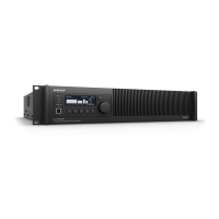
Bose FREESPACE BMA-125

Bose FREESPACE BMA-125
49 pages
To Next Page IconTo Next Page
Loading...
1
Table of Contents
SAFETY INFORMATION ................................................................................................................... 2
Electrostatic Discharge Sensitive (ESDS) ..................................................................................... 3
120V Version Specifications ........................................................................................................ 4-5
230V Version Specifications ........................................................................................................... 6
120V Disassembly/Assembly Procedures .................................................................................. 7-9
230V Disassembly/Assembly Procedures .............................................................................. 10-12
BMA-125 Test Procedures 120V .............................................................................................. 13-16
BMA 125 Test Procedures 230V.................................................................................................... 16
Part List Notes................................................................................................................................ 17
120V Main Assembly Part List ...................................................................................................... 18
Figure 1. 120V Chassis Layout ...................................................................................................... 19
120V Amp PCB Part List ........................................................................................................... 20-22
120V Tone/Volume Control PCB Part List ............................................................................... 23-24
120V Equalizer PCB Part List................................................................................................... 25-26
230V Main Assembly Part list .................................................................................................. 27-28
230V Amp PCB Part List ........................................................................................................... 29-31
230V Tone/Volume/Equalizer PCB Part List............................................................................ 32-35
Input Module 2B37 Part List.......................................................................................................... 36
Input Module 2B50 Part List..................................................................................................... 37-38
Figure 2. 2B37 Schematic and PCB Layout................................................................................... 39
Figure 3. 2B50 Schematic and PCB Layout................................................................................... 40
Figure 4. 120V Driver PCB Layout................................................................................................. 41
Figure 5. 120V Tone/Volume Control PCB Layout ......................................................................... 41
Figure 6. 120V Equalizer PCB Layout (Solder Side) ..................................................................... 42
Figure 7. 120V Equalizer PCB Layout (Component Side) ............................................................. 42
Figure 8. 230V Driver PCB Layout................................................................................................. 43
Figure 9. 230V Tone/Volume/Equalizer PCB Layout .................................................................... 44
Figure 10. and 11. 230V wiring diagram ................................................................................... 45-46
Question and Answer IconNeed help?

Do you have a question about the Bose FREESPACE BMA-125 and is the answer not in the manual?

Bose FREESPACE BMA-125 Specifications

General IconGeneral
Weight4.1 kg (9.0 lb)
Output Channels2
Gain32 dB
Input Impedance10kΩ
THD+N< 0.04 % (at full rated power)
Input Channels2
Output Impedance4Ω - 8Ω
Total Harmonic Distortion< 0.04 % (at full rated power)
Signal-to-Noise Ratio100 dB (below rated power, 20 Hz - 20 kHz)

Summary

Safety Information

Safety Procedures

Details on leakage current and insulation resistance tests.

Electrostatic Discharge Sensitive (ESDS) Device Handling

ESDS Handling Precautions

Guidelines for handling ESDS components to prevent damage.

120 V Version Specifications

Performance Specifications

Covers Power Output, Regulation, Input Sensitivity, Load Voltage, and Outputs.

Response and Control Specifications

Details Frequency Response, Bandwidth, S/N Ratio, and Tone Controls.

Operational and Physical Specifications

Covers Mute, Control Interaction, Power Consumption, Temp, Size, Weight, Modules.

230 V Version Specifications

Performance Specifications

Covers Power Output, Regulation, Input Sensitivity, Output Impedance, and Outputs.

Response and Control Specifications

Details Frequency Response, Bandwidth, S/N Ratio, and Tone Controls.

Operational and Physical Specifications

Covers Mute, Control Interaction, Power Consumption, Temp, Size, and Weight.

120 V DisassemblyAssembly Procedures

Top Cover and Input Module Procedures

Steps for removing and replacing the unit's top cover and input modules.

ToneVolume PCB and Potentiometer Procedures

Steps for removing and replacing the Tone/Volume PCB and associated controls.

Driver PCB and Equalizer PCB Procedures

Steps for removing and replacing the Driver and Equalizer PCBs.

Transformer and Transistor Procedures

Steps for removing and replacing transformers and output transistors.

230 V DisassemblyAssembly Procedures

Top Cover and Input Module Procedures

Steps for removing and replacing the 230V unit's top cover and input modules.

ToneVolumeEqualizer PCB and Potentiometer Procedures

Steps for removing and replacing the 230V PCB and associated controls.

Driver PCB and Transformer Procedures

Steps for removing and replacing the 230V Driver PCB and transformers.

Transistor, Heat Sink, and Fuse Procedures

Steps for removing and replacing transistors, heat sinks, and fuses.

BMA-125 120 V Test Procedures

Setup, Controls, and 48 Output Tests

Initial setup, controls, and testing of 4Ω and 8Ω outputs.

Voltage Output and TapeMixer Tests

Testing 25V, 70V outputs, Tape, and Mixer outputs.

Line Output, Volume, Mute, and Mic Input Tests

Testing Line Output, Volume Range, Mute, and Mic Inputs.

Additional Input and EQ Tests

Testing Inputs 3, 4, MIC PAGE, and EQ modes.

230 V Variation Tests

230 V Remote Volume and 100 V Output Tests

Testing Remote Volume and 100V output for 230V version.

Part List Notes

Notes on Part Availability and Safety

Information on part ordering and critical safety replacement parts.

120 V Main Assembly Part List

Main Assembly Component List

List of components for the 120V main assembly.

Figure 1. 120 V Chassis Layout

120 V Chassis Component Diagram

Visual layout of components on the 120V chassis.

120 V AMP PCB

AMP PCB Resistors

List of resistors used on the 120V AMP PCB.

AMP PCB Capacitors, Diodes, Transistors

List of capacitors, diodes, and transistors on the 120V AMP PCB.

120 V ToneVolume Control PCB

ToneVolume PCB Resistors

List of resistors for the 120V Tone/Volume Control PCB.

ToneVolume PCB Capacitors, Transistors, ICs, Misc.

List of capacitors, transistors, ICs, and miscellaneous parts.

120 V Equalizer PCB

Equalizer PCB Resistors, Capacitors, ICs

List of resistors, capacitors, and ICs for the 120V Equalizer PCB.

Equalizer PCB Miscellaneous Components

List of miscellaneous parts for the 120V Equalizer PCB.

230 V Main Assembly Part List

230 V Main Assembly Component List

List of components for the 230V main assembly.

230 V Main Assembly Part List (continued)

230 V Power Cords and Input Modules

List of power cords and input modules for the 230V version.

230 V AMP PCB

AMP PCB Resistors

List of resistors for the 230V AMP PCB.

AMP PCB Transistors, ICs, and Diodes

List of transistors, ICs, and diodes for the 230V AMP PCB.

AMP PCB Miscellaneous Components

List of miscellaneous parts for the 230V AMP PCB.

230 V ToneVolumeEqualizer PCB

ToneVolumeEqualizer PCB Resistors

List of resistors for the 230V Tone/Volume/Equalizer PCB.

ToneVolumeEqualizer PCB Capacitors

List of capacitors for the 230V Tone/Volume/Equalizer PCB.

ToneVolumeEqualizer PCB Transistors, ICs, Diodes

List of transistors, ICs, and diodes for the 230V PCB.

ToneVolumeEqualizer PCB Miscellaneous Components

List of miscellaneous parts for the 230V Tone/Volume/Equalizer PCB.

Input Module 2 B37 Part List

2 B37 Module Components

List of resistors, capacitors, ICs, and miscellaneous parts for Module 2B37.

Input Module 2 B50 Part List

2 B50 Module Components

List of resistors, capacitors, ICs, diodes, and miscellaneous parts.

2 B50 Module Miscellaneous Components

List of miscellaneous parts for Module 2B50.

Figure 2. 2 B37 Schematic and PCB Layout

2 B37 Schematic and PCB Diagram

Schematic and PCB layout for Input Module 2B37.

Figure 3. 2 B50 Schematic and PCB Layout

2 B50 Schematic and PCB Diagram

Schematic and PCB layout for Input Module 2B50.

Figure 4. 120 V Driver PCB Layout

120 V Driver PCB Layout

Printed circuit board layout for the 120V Driver PCB.

Figure 5. 120 V ToneVolume Control PCB Layout

120 V ToneVolume Control PCB Layout

PCB layout for the 120V Tone/Volume Control PCB.

Figure 6. 120 V Equalizer PCB Layout (Solder Side)

120 V Equalizer PCB Solder Side Layout

PCB layout showing component placement on the solder side.

Figure 7. 120 V Equalizer PCB Layout (Component Side)

120 V Equalizer PCB Component Side Layout

PCB layout showing component placement on the component side.

Figure 8. 230 V Driver PCB Layout

230 V Driver PCB Layout

Printed circuit board layout for the 230V Driver PCB.

Figure 9. 230 V ToneVolumeEqualizer PCB Layout

230 V ToneVolumeEqualizer PCB Layout

PCB layout for the 230V Tone/Volume/Equalizer PCB.

Figure 10. 230 V Wiring Diagram (Part 1)

230 V Wiring Diagram - Part 1

First part of the 230V unit wiring diagram.

Figure 11. 230 V Wiring Diagram (Part 2)

230 V Wiring Diagram - Part 2

Second part of the 230V unit wiring diagram.

Related product manuals