17
1. S
2. I
3. G
M
rvice Test
put Conne
in Shadin
untin
Ho
anel
tors
Kit
es
1
2
3
3
TEST PROCEDURES
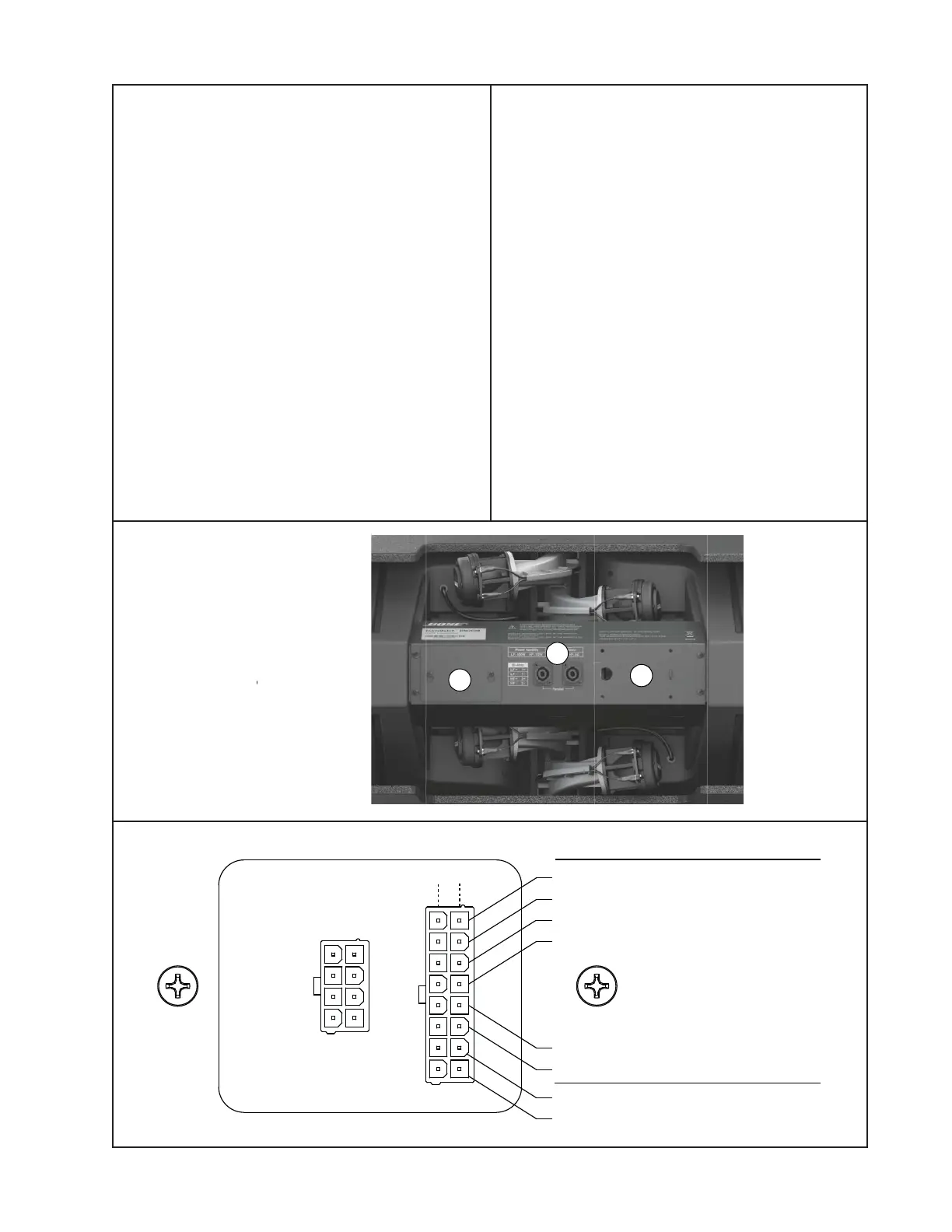
1. Driver DC Resistance Test
Note: This test will verify that the voice coils
for the tested drivers are in the correct DC
resistance range. Use this test if you suspect
a driver with a failed voice coil.
1.1 Loosen the two screws that secure the
Service Access Panel (1 below) to the Input/
Output Panel. Slide the panel over the
screws and lift it off.
1.2 Once you have removed the access
panel, you will see a PCB with two connec-
tors on it. Unplug the 8 pin input connector
from the left hand connector on the I/O PCB.
1.3 The connector on the right hand side of
the board has connections to each individual
driver. Using a digital multimeter, measure
the DC resistance of each driver at the
points shown in the diagram below.
Note: The HF-1 to HF-6 drivers are the
compression drivers, and are numbered
1 - 6 from top to bottom. The LF10 drivers
are the woofers, left and right as you face
the front of the speaker.
1.4 Verify that the DC resistance values are
within the ranges shown below in the dia-
gram. If they are not, check the wiring har-
ness for damage or broken connections to
the drivers. If the harness is okay, replace
the failed driver.
1.5 Reconnect the 8 pin input harness and
reattach the access panel.
+
-
EMB2 (1)
EMB2 (2)
EMB2 (3)
EMB2 (4)
EMB2 (5)
EMB2 (6)
LF10 (Left)
LF10 (Right)
Driver DC Resistance
4.9Ω
± 0.3Ω
4.9Ω
± 0.3Ω
6.3Ω
± 0.7Ω
Polarity