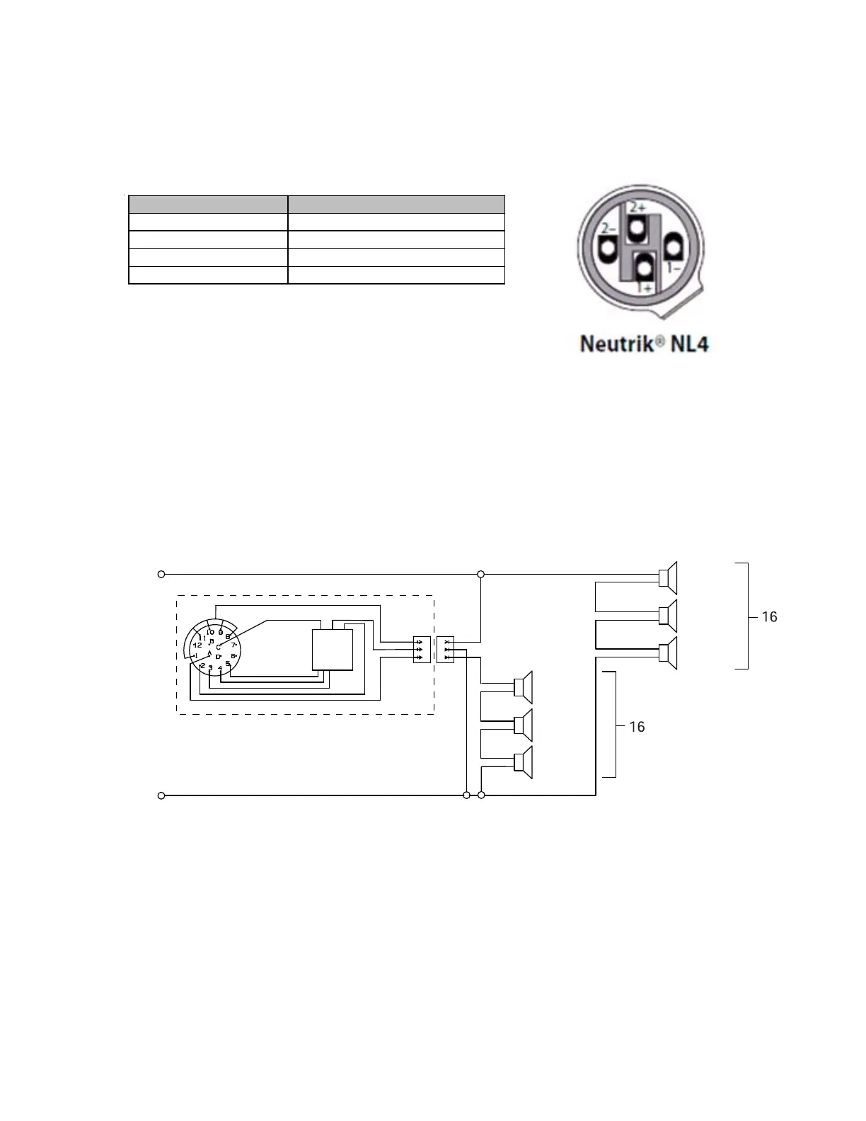
19
Connector Wiring
The RoomMatch
®
array module is equipped with two (2) Neutrik
®
NL4 connectors wired in
parallel to allow loop-through connection to an additional module. The connector is wired to
provide separate amplifier channels to the high-frequency (HF) and low-frequency (LF) transduc-
ers as follows:
NL4 Connector Pin Driver Bandpass Section
1+ LF drivers -
ositive
1 - LF drivers - ne
ative
2+ HF drivers - positive
2 - HF drivers - ne
ative
Optional Gain-Shading Kit Installation
An optional gain shading kit (RMSHADE) is available for RoomMatch™ modules to attenuate the
lower-3 compression drivers relative to the upper-3 drivers. This option may provide more
uniform coverage in array configurations with large changes in directivity index from module to
module. An electrical diagram for the mid/high compression drivers illustrating the gain shading
kit circuit is shown below.
Electrical Diagram of Compression Drivers with Gain Shading Kit Installed
2-
2+
EMB2
(1)
EMB2
(2)
EMB2
(3)
EMB2
(4)
EMB2
(5)
EMB2
(6)
Transformer
Pin 5 -6.0dB (BLU)
Pin 4 -4.5dB (RED)
Pin 3 -3.0dB (BRN)
Pin 2 -1.5dB (WHT)
Transformer In (YEL)
Transformer Out (ORG)
Input (YEL)
Output (ORG)
Ground (BLK)
Gain Shading Kit
Pin 1 0.0dB (DIRECT)
[Transformer Disconnect]