Creating a Patch
9
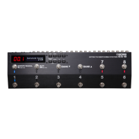
Editing the Settings of a Patch (Memory
Edit Mode)
Quick Edit
Here’s how you can turn the eect loops on/o and save the settings
by operating only the switches.
1. Recall the patch that you want to edit.
2. Hold down the [MEMORY/MANUAL] switch for two
seconds or longer.
The MEMORY/MANUAL indicator blinks blue; the ES-8 is in memory
edit mode.
3. Use number switches [1]–[8] to turn each eect loop on/
o.
4. Press the [MEMORY/MANUAL] switch.
5. Use the [BANK
I
] [BANK
H
] switches and number switches
[1]–[8] to select the save-destination.
6. Press the [MEMORY/MANUAL] switch.
If you decide to cancel, press the [MUTE] switch.
When the settings are saved, the MEMORY/MANUAL indicator
changes to steadily lit blue.
Basic Operation
1. Recall the patch that you want to edit.
2. Press the [EDIT] button.
3. Use the [
K
] [
J
] buttons to select “Patch” or “CTL/EXP,” and
press the [ENTER] button.
(Example)
Loop On/Off
[ENTER]
4. Use the [
K
] [
J
] buttons to select a category, and press the
[ENTER] button.
(Example)
Input
Sel:1|Buf:OFF _
5. Use the [
K
] [
J
] buttons to move the cursor, and use the [–]
[+] buttons to specify its value.
6. To save the edited settings, write the patch.
To cancel without saving, press the [DISPLAY/EXIT] button several
times.
Parameter List
Patch
Parameter Value/Explanation
Patch Name Up to 16 characters
Loop On/O
You can turn each eect loop on/o. When on, a “
” icon is shown.
* You can also turn them on/o by pressing the number
switches [1]–[8].
8 7 6 5 4 3 2 1
_
Loop Structure
Carry Over
You can make the following settings. For details on operation,
refer to “Changing the Eect Loop Settings” (p. 8).
5 Connection order of each eect loop
5 Parallel connection settings
5 Connection position of volume loop
5 Carry Over setting
* Depending on the settings, there are cases in which parallel
connection is not possible, or in which Carry Over does not
work.
=8=7- -5-4-2-1-V
3
_
CTL1–6
Specify the control signals that are sent from the EXT CTL CTL
1/2–5/6 jacks when you switch patches.
The available control signals depend on the Play Option/CTL1–6
setting (p. 12).
For LAT
OFF Sends “o”
ON Sends “on”
For PLS
OFF
Sends a short (100 ms) pulse when changing
between “o” and “on.”
* If the display of the ES-8 diers from the
state of the connected equipment, switch
the state of the connected equipment.
ON
For TP2–4
OFF Sends nothing
ª
–
˜
Sends tempo at the interval of the specied
note value according to the Master BPM value
* Depending on the Master BPM setting,
there are cases in which this cannot be
sent.
20–500
Sends the specied tempo (
¸
=)
EXP1, 2
Specify the control signals that are sent from the EXT CTL EXP 1–2
jacks when you switch patches.
0–127 The specied value is sent.
EXP1, 2
The current value of the expression pedal
connected to the CTL IN jack is sent.
Input Sel
Selects the input.
1 IN 1 jack is selected.
2 IN 2 jack is selected.
Input Buf
Turns the input buer on/o (p. 19).
ON, OFF
Output Sel
Selects the output destination.
1, 2
The sound is output from the OUT 1/L or OUT
2/R jack.
1&2
The sound is output from both the OUT 1/L
and OUT 2/R jacks (stereo output).
Output Buf
Turns the output buer on/o (p. 14).
ON, OFF
Output Gain
This is the output gain. It is used only if Output Buf is ON.
0 dB, +2 dB, +4 dB, +6 dB
Master BPM
Species the patch’s BPM.
20–500