Do you have a question about the Boss MX1-3HL and is the answer not in the manual?
Explains symbols (DANGER, CAUTION) and typography conventions used throughout the manual.
Provides the official website and contact details for additional support and information.
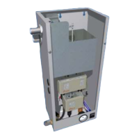
Details the internal arrangement and operational flow of the BOSS pressurisation unit.
Guidelines for installing the equipment in a suitable environment, including frost-free areas and access.
Crucial safety warnings regarding electrical connections, live terminals, and protective covers.
Describes the intended use of the unit for sealed heating and cooling systems with expansion vessels.
Information on setting the minimum static pressure and dependence on pump sets.
Instructions for making pipe connections, including flushing mains supply and avoiding specific valve types.
Step-by-step guide for installing the mini mechanical units, including connections and settings.
Explains the selection and installation of flow restrictors based on mains water pressure to prevent damage.
Specifies the required physical clearances and connection sizes for the Mini MX-HL models.
Details the fuse and terminal block connections for the main power supply.
Explains power connection via a fused spur for larger models.
Recommends using a lockable isolator for safe power supply to the unit.
Warns about potential damage from high voltages during electrical installation testing.
A checklist of essential conditions to meet before starting the commissioning process.
Outlines the step-by-step procedure for commissioning the pressurisation unit.
Explains the range and differential settings for the pressure control switch.
Details the pre-set and adjustable high/low pressure switch settings for boiler control.
Instructions on how to adjust the range and differential settings on the pressure switches.
Steps for hydraulic commissioning, focusing on the float valve and initial start-up.
Describes how to test the unit's operation by simulating a minor leak.
Provides a timeline for routine maintenance tasks, including initial checks and annual inspections.
Directs users to the troubleshooting section for identified faults and spare parts for replacements.
Illustrates the wiring configuration for single pump units.
Illustrates the wiring configuration for twin pump units.
Shows the wiring connections for boiler control (IN/OUT).
Identifies internal components of the Mini Models (MX1-3HL, MX2-3HL) with a front view diagram.
Lists internal components with descriptions and corresponding part codes for ordering.
Provides a guide to diagnose and resolve common faults and issues with the pressurisation unit.
Forms for recording details of annual service checks, including range and differential settings.
Explains what is covered under the BOSS warranty, including manufacturing defects.
Details conditions not covered by the warranty, such as misuse or incorrect installation.
Outlines the specific conditions and timescales for the warranty, including DOS and DOC.
| Brand | Boss |
|---|---|
| Model | MX1-3HL |
| Category | Industrial Equipment |
| Language | English |