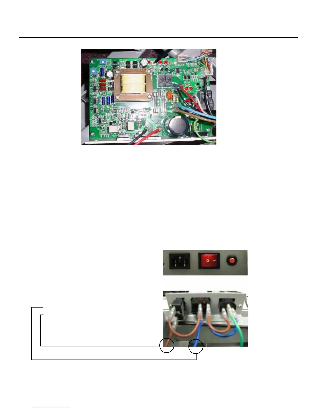
Electrical Layout
1. Top Black cable (speed sensor)
2. Middle Red wire (up elevation)
3. Middle Black wire (down elevation)
4. Middle White wire (elevation Com)
5. Blue wire (N/L2)
6. Brown Wire (AC/L1)
7. Bottom Left Black wire (A2 Motor)
8. Bottom Right Red wire (A1 Motor)
Lights
1. Top Left (PWM)
2. Top Middle (speed sensor)
3. Top Right (V_Console)
Lights next to Middle Red wire
1. Left (elevation up)
2. Right (elevation down)
Fuses
1. Middle Left ( 0.5 amp main board)
2. Middle Right ( 1. 5 amp AC – incline)
3. Gray Fuse under Blue and Brown wire
(15 amp DC power)
Plug and Switch configuration
Plug and switch wiring
configuration
1. Connects with N/(L2) On control board
2. Connects with AC/(L1) On control board
Service Manual
6