Do you have a question about the Bowflex Sport 001-6961 and is the answer not in the manual?
Guidance on selecting an appropriate assembly location and ensuring adequate workout space for safe operation.
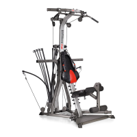
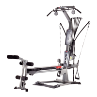
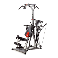
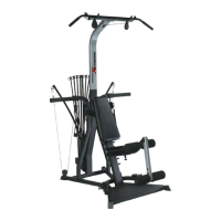
A comprehensive list of all numbered components included with the Bowflex Sport® home gym for assembly.
A detailed list of all hardware items, identified by item number and description, required for assembly.
A list of accessories provided with the Bowflex Sport® home gym, such as grips, bars, and cables.
List of essential tools required for assembling the Bowflex Sport® home gym, available at local stores.
Connects the Lower Lat Tower to the Base Platform using specific screws, washers, and nuts.
Attaches the left and right base legs to the main assembly using screws and washers.
Secures the squat platform to the main assembly using screws, washers, and bolt covers.
Connects the chest bar with pulleys to the lower lat tower using screws, washers, and nuts.
Attaches the seat bracket to the seat pad using screws and washers for the seat assembly.
Connects the seat rail to the seat assembly, allowing the seat to slide and adjust.
Attaches the rear leg component to the rear leg cross tube using screws, washers, and nuts.
Connects the rear leg assembly to the seat rail assembly, ensuring proper movement and engagement.
Secures the seat rail assembly to the main assembly's rail bracket using a screw, washers, and a knob.
Attaches the leg extension pivot tube to the bracket on the rear leg using a screw, washers, and a lock-out pin.
Installs foam rollers and chrome roller tubes onto the leg extension pivot tube and rear leg.
Connects the leg cable to the leg extension pivot tube using a screw, washers, and a lock nut.
Assembles the leg extension seat pad and support tube using screws and washers.
Connects the assembled leg extension seat to the main assembly by hooking brackets onto rollers.
Attaches the lat cross bar to the upper lat tower bracket using screws, washers, and nuts.
Connects the upper lat tower to the lower lat tower using screws, washers, and nuts.
Secures the rod box with power rods into the rod box frame using screws and washers.
Attaches the rod box frame assembly to the lat tower above the chest bar using screws, washers, and nuts.
Attaches the faceplate to the lower lat tower by inserting stems and securing with screws.
Secures the faceplate back panels to the faceplate using screws, completing the faceplate assembly.
Adjusts and tightens the lower bolt on the seat bracket to ensure smooth seat movement.
Explains how to attach and release the bench pad from the seat assembly via a half hinge mechanism.
Illustrates how to route and connect the rod cables, hand grips, and snap hooks to the chest pulley system.
Details routing lat cables from pulleys on the cross bar to hand grips or the lat bar.
Guides on unwrapping and connecting the leg cable from the rear leg pulley to the rod cable.
Explains routing squat cables from base leg pulleys to the chest bar and squat bar.
Contact details for Nautilus customer service and innovation centers located within the United States.
Contact information for Nautilus offices in various countries outside the United States for global support.