NOTE: The battery circuit breaker must be turn to “1” position when a voltage comes to the main.
If not in a second main failure the critical load will be without Voltage.
C. On maintenance by-pass: UPS shutdown but the load connected to the unprotected mains via
the maintenance by-pass supply line.
D. Parallel operation : At least 2 UPS’s is installed to system for increasing security and redundancy
, they operates together and interactive.
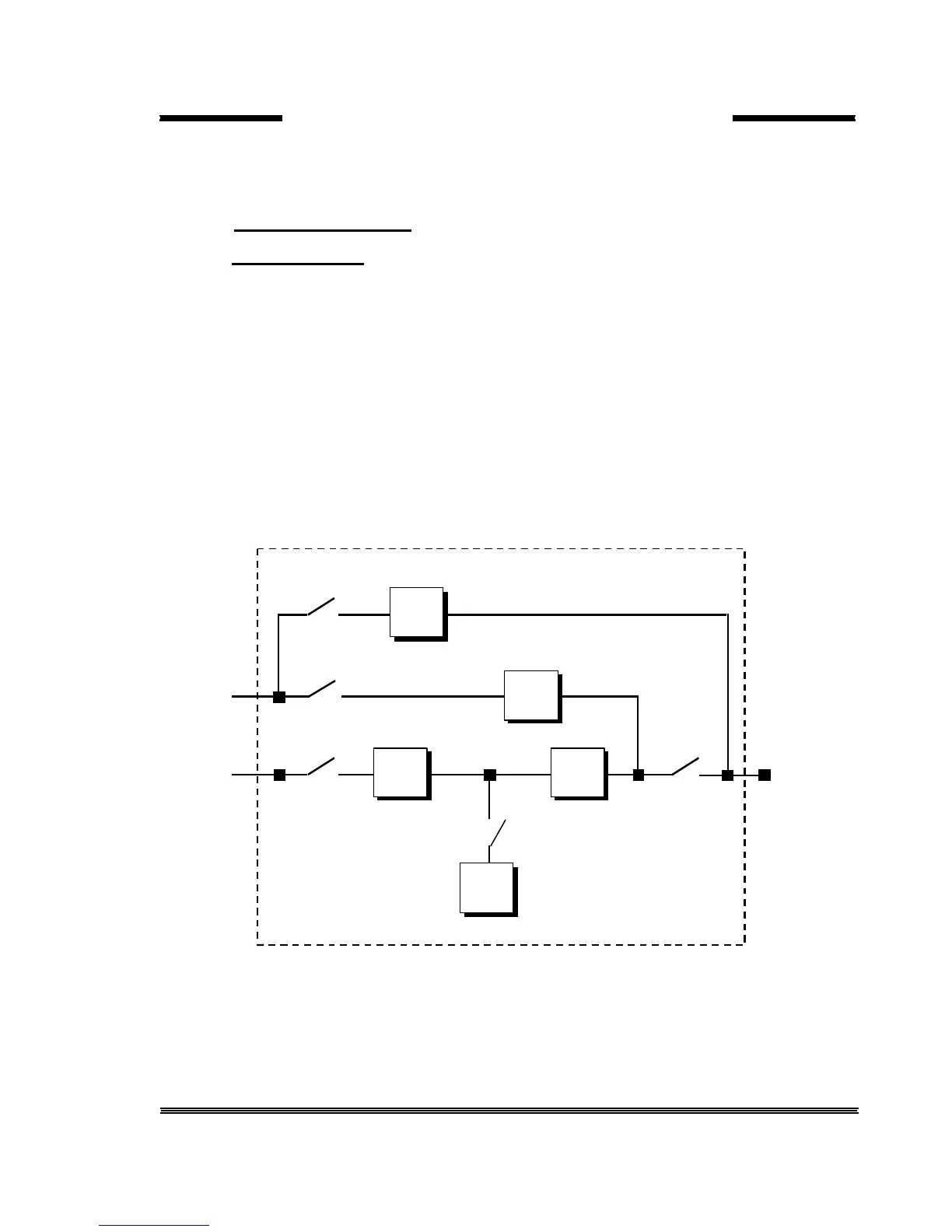
1.2.2 The Power Configuration of UPS
The power switch location of the T-300P series UPS’s are shown in the figures 1.1-2-3-4 In the figure 1.2
external (split) by-pass block diagram is given. Optionally the static and mechanic by-pass line can be
connect to a different 3 phase AC source ( other UPS etc.),and the rectifier input is connected to generator or
mains voltage. If there is no other power supply static and mechanic by-pass line input (S2) and the rectifier
input connections will be connect to each other. (See figure 1.1)
During the normal operation except the maintenance by-pass switch, all the Switches will be at “1-On”
position (closed).