1
VSB/200C
BLOCK SELECTOR
The VSB/200C block selector
combined with the SI/200 o
VSI/200 entrance selectors, ena
bles coded call audio and video
residential multi-block installation
to be created.
A residential installation is made
up of one or more main entr
panels from where the users of the
various blocks can be called, each
of which may have its own entr
panel from where the users of the
block can be called.
When idle, the VSB/200C plu
SI/200 or VSB/200C plus VSI/200
selector unit connects the users o
the block with their own entr
panel.
The switching of the selector unit i
controlled by coded call signals. In
order to be able to recognize said
signals, the unit must have been
suitably programmed.
Programming is performed by sen
ding two codes, which define the
two limits of the call group which
are recognized by the VSB/200C.
In the event of calls coming from
the main entry panel, the selecto
unit establishes the communica
tion between the receiver called
and the main entry panel, cutting
off the entry panel of the block in
question, in which an engaged
signal appears.
When a block installation is activa
ted, the call from the main entr
panel to a user in that block i
unsuccessful and the engaged
indicator on the main entry pane
will be activated for as long as the
call button is kept pressed down
plus an additional two second
approx.
Programming one block only
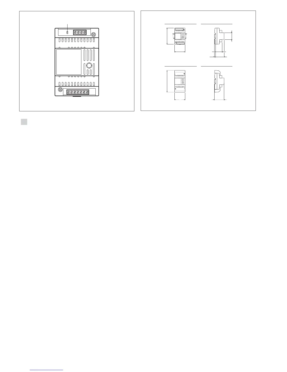
1 - Power up the unit and remove
the SW1 programming jumper
figure 1.
2 - Send the five-digit code, where
the first two digits identify the bloc
to be programmed, and the othe
GB
INSTALLATION
INSTRUCTIONS
3 - Wait for the programming to be
acknowledged (only if the VPD/100
or VPDM/100 switchboard is being
used).
4 - Insert the SW1 programming
jumper.
Programming a range
of progressive codes
1 - Power up the unit and remove
the SW1 programming jumper,
figure 1.
2 - Send the code relating to the
first receiver (code with the lowest
value).
3 - Wait for the programming to be
acknowledged (only if the VPD/100
or VPDM/100 switchboard is being
used).
4 - Send the code relating to the
last receiver (code with the highest
value).
5 - Wait for the programming to be
acknowledged (only if the VPD/100
or VPDM/100 switchboard is being
used).
6 - Insert the SW1 programming
jumper.
Programming one call only
1 - Power up the unit and remove
the SW1 programming jumper,
figure 1.
2 - Send the code to be recorded.
3 - Wait for the programming to be
acknowledged (only if the VPD/100
or VPDM/100 switchboard is being
used).
4 - Send the same code again.
5 - Wait for the programming to be
acknowledged (only if the VPD/100
or VPDM/100 switchboard is being
used).
6 - Insert the SW1 programming
jumper.
NOTE. If the programming is car-
ried out via the VPD/100 or
VPDM/100 porter switchboard, the
acknowledgement of the comple-
ted programming is given by the
codes sent appearing on the
display PORTER CALL.
,
The unit can be installed without
terminal covers, in boxes fitted wit
DIN rail (EN 50022).
See figure 2A for overall dimen
sions.
Alternatively, it can be wall-moun
ted using the DIN rail provided
and applying the terminal cover.
See figure 2B for overall dimen
43,5
45
7,5
57
70
106
A
B
64,5
70
145
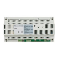
Function of each terminal, figure 1
Terminal block B
5 ground
7 coded call from main entry
panel
12 coded call to porter switch-
board
N2 enabling of second call note
Terminal block F
5 ground
7 coded call from block’s entry
panel
8 call common
12 call to porter switchboard
21 +12 VDC
24 block engaged
N2 enabling of second call note
Technical features
• Supply voltage: 11÷13 VDC.
• Current demand: 8 mA
• Maximum number of blocks
which can be connected in a sin-
gle installation: 100
• Working temperature range: from
0 °C to 35 °C.
• Dimensions: 4 DIN units, low-
profile module, figure 2.
DISPOSAL
Do not litter the environment wit
packing material: make sure it i
disposed of according to the regu
lations in force in the country wher
the product is used.
When the equipment reaches th
end of its life cycle, take measure
to ensure it is not discarded in th
environment.
The equipment must be dispose
of in compliance with the regula
tions in force, recycling its compo
nent parts wherever possible.
Components that qualify as recy
clable waste feature the relevan
symbol and the material’s abbre
 Loading...