3
PULSANTE DI CHIAMATA
CALL BUTTON CD
RUFTASTE
BOUTON D’APPEL
PULSADOR DE LLAMADA
BOTÃO DE CHAMADA 123456789
1 XXXXX0XXX
2 XXXX0XXXX
3 XXX0XXXXX
4 XX0XXXXXX
5 X0XXXXXXX
6 0XXXXXXXX
7 XXXXX00XX
8 XXXX0X0XX
9 XXX0XX0XX
10 XX0XXX0XX
11 X0XXXX0XX
12 0XXXXX0XX
Fig. 4
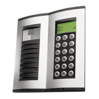
jumper SW2, figure 2, is placed to
position C the relay is controlled
by the coded signal sent either by
the entry panel or porter swirch-
board.
When jumper SW2 (fig. 2) is pla-
ced to position INT the relay is
controlled by the coded signal
sent by a intercom call button on
intercom receivers series.
The duration the relay stays ener-
gized depends of jumper SW3,
figure 2. When SW3 is placed to
position t the time can be regula-
ted by means of potentiometer P1,
figure 1, from about 0.6 sec. to 10
sec., after which it de-energizes
even if the code is still sent.
When SW3 is placed to position T
the relay remains energized, after
the time preset by P1 has ela-
psed, if the coded signal is still
present.
NOTE. Take off top frame to reach
SW2 and SW3 jumpers.
The acces key to VLS/100C is con-
trolled by jumpers CD, figure 1.
The code to be set on VLS/100C
must much that of controlling unit,
i.e.:
- When VLS/100C is controlled by
entry panel or porter switchboard
refer to tables in relevant instruc-
tions sheet.
- When VLS/100C is controlled by
intercom receivers refer to table
in figure 4.
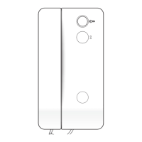
Functions to be set
P1 Potentiometer to preset the
time VLS/100C stays ener-
gized.
CD Access key jumper.
SW2 Jumper to select VLS/100C
driving source:
- When placed to position C
the relay is controlled by
entry panel or porter switch-
board.
- When placed to position
INT the relay is controlled
by intercom receivers.
SW3 Duration relay stays energi-
zed:
- When placed to position t
the relay stays energized for
the time preset by P1.
- When placed to position T
the relay remains energi-
zed, after the time preset by
P1 has elapsed, if teh
coded signal is still present.
DL1 Test LED.
The LED, figure 1, is lit for
the duration the relay is
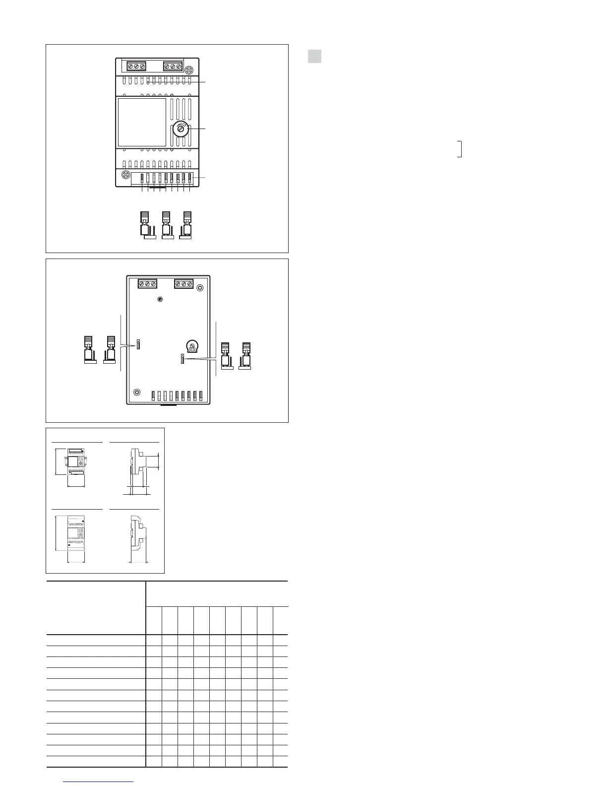
terminal covers into boxes provi-
ded with DIN rail (EN 50022).
Dimensions are shown in figure
3A.
It can also be surface mounted,
using the DIN rail supplied, but
fitted with terminal covers.
Dimensions are shown in figure
3B.
1
GB
INSTALLATION
INSTRUCTIONS
VLS/100C.
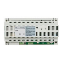
01 RELAY UNIT
VLS/100C is a relay designed to
control auxiliary services. When
VLS/100C
Function of each terminal
Terminal block A
1 normally open contact
2 common
3 normally closed contact
Terminal block B
5 <
supply voltage 14÷17,5VDC
6 +
7 input of coded signal
Technical features
• Supply voltage: 14÷17,5VDC.
• Current demand: 60mA.
• Max. load to relay contact 250V,
5A (2A if load is inductive).
• Working temperature range:
from 0 °C to +35 °C.
• Dimensions: 4 DIN units modu-
le, low profile (fig. 3).
 Loading...