43,5
45
7,5
57
70
106
A
B
64,5
70
145
1
2
BPT S.p.A.
30020 Cinto Caomaggiore
Venezia - Italy
GB
INSTALLATION
INSTRUCTIONS
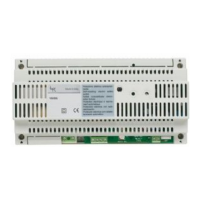
RELAY MODULE VLS/101
The relay can be used to control
auxiliary services such as: stairs
light, additional bell, etc.
The relay coils can be energized
with AC/DC voltage (10 ÷ 24 V) or
through low level signals e.g. call
signal.
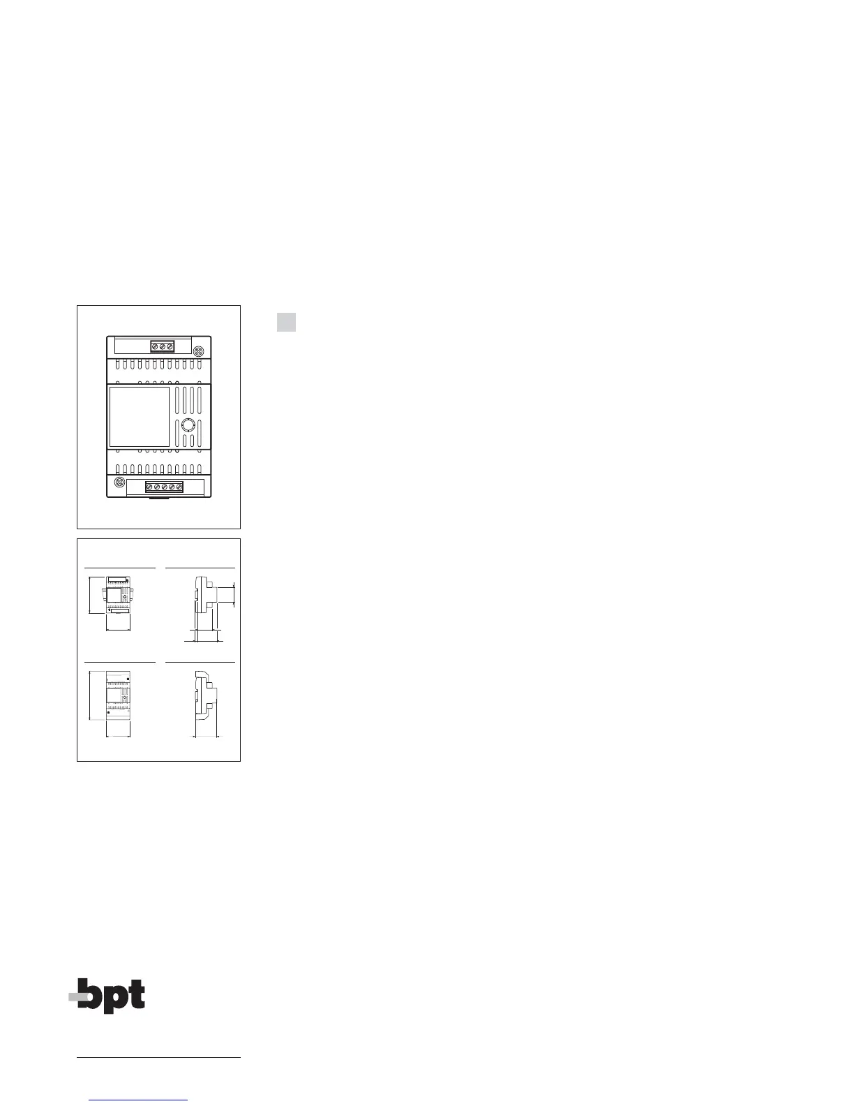
Function of each terminal (fig. 1)
Terminal block A (relay’s contacts)
1 normally open
2 common
3 normally close
Terminal block B
VLS/101 used as auxiliary relay:
1-2 voltage supply to relay’s coi
(10 ÷ 18 V DC/AC) or
1-3 voltage supply to relay’s coi
(18 ÷ 24 V DC/AC)
VLS/101 used as call adapter:
1 +10 ÷ 18 V DC
or
3 +18 ÷ 24 V DC
4 call signal input
5 ground
Technical features
• Supply voltage: 10 ÷ 24 V DC/AC
or low level signal (e.g. cal
signal).
• Current demand: 60 mA max.
• Max load to relay contact: 5 A a
250 V (2 A if load is inductive).
• Working temperature range: from
0 °C to + 35 °C.
• Dimensions: 4 DIN units module
low profile (fig. 2).
The unit can be installed withou
terminal covers into boxes provi-
ded with DIN rail (EN 50022).
Dimensions are shown in figure 2
A.
It can also be surface mounted
using the DIN rail supplied, but fit-
ted with terminal covers.
Dimensions are shown in figure 2
B.
 Loading...