MOUNTING KIT INSTALLATION
617 TRENCHER
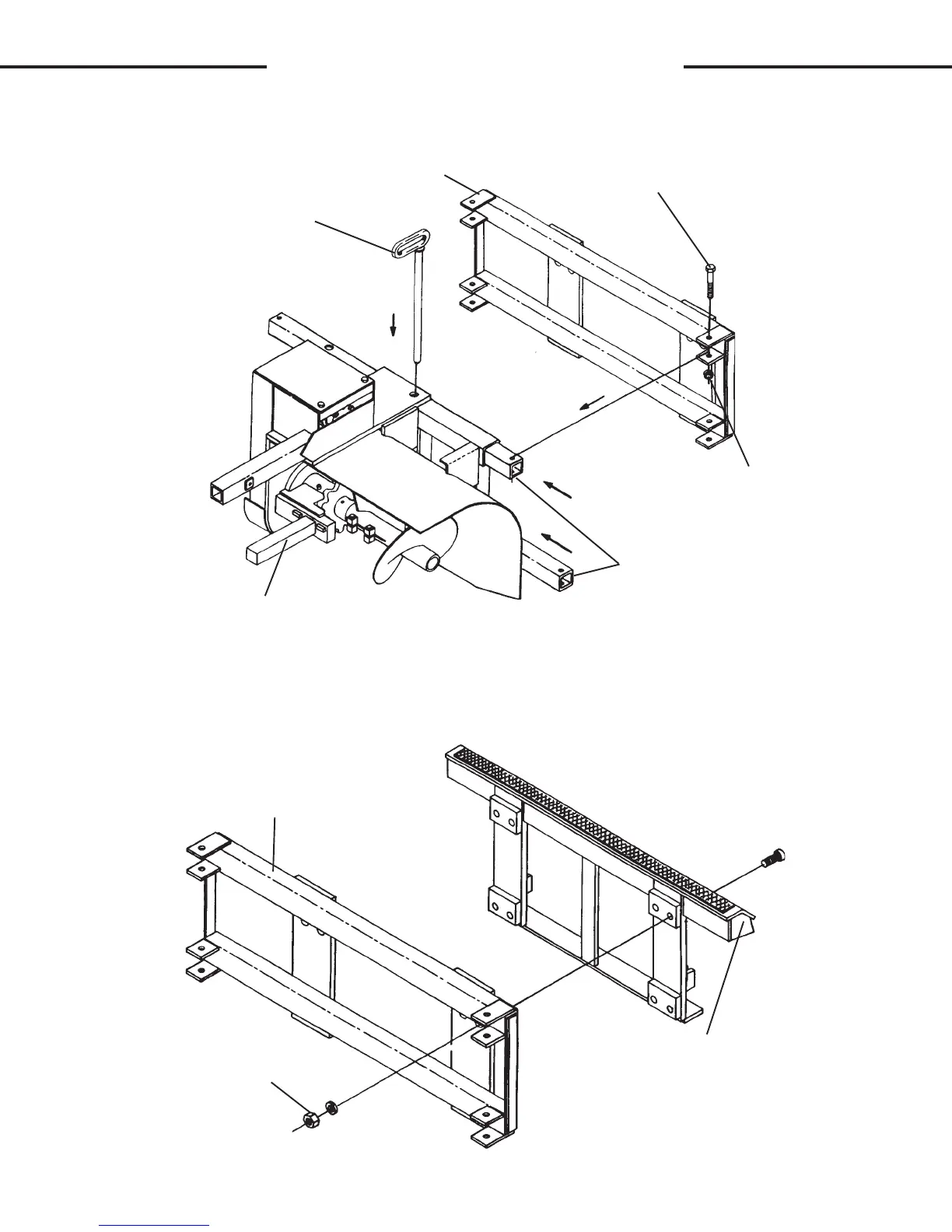
FIGURE #1
SIDE SHIFT MOUNTING FRAME
LOCK PIN
SIDE SHIFT INNER TUBES
.75"UNC LOCK NUT
BASIC TRENCHER ASSEMBLY
.75"UNC X 4.50 CAPSCREW
.75" HARDWARE
ATTACHING BRACKET
SIDE SHIFT MOUNTING FRAME
3. Mount the attaching bracket(s) to the side shift mounting frame on the tren-
cher using the .75" hardware provided. Use the mounting kit assembly
diagram and parts list at the front on this section as a reference for the
correct hardware needed. (See Figure #2)
5778
2-21-92
FIGURE #2
E
E