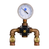
EFX 60/S19-2200 Installation
2 4-19-2011 Bradley Corporation • 215-1289 Rev. L; EN 10-09-018
Supplies recommended for installation
• Lockable shut-off on the outlet if tempered water is supplied to one or more emergency fixtures
• Lockable shut-off on the inlets/supplies
• (6) 3/8" wall anchors and fasteners for surface-mounted cabinet
• (4) 1/4" fasteners (and wall anchors, if necessary) for recess-mounted cabinet
• Unions on all connections to facilitate removal of valve
Tools required for temperature adjustment
• 5/32" Allen wrench
• Blade screwdriver
1
Install Optional Cabinet (If not installing cabinet, skip to Step 2)
Recessed Cabinet:
1. Rough-in wall opening 24-1/2" W x 28-1/2".
2. Insert the cabinet and secure to wall with four 1/4" fasteners
properly anchored (supplied by installer.)
3. Install two anchors and screws through the valve bracket in
back of the cabinet into a secure brace (supplied by installer) or
into wall. This will support the valve.
4. Install the valve nipples and one-half of the union ball valve
using pipe sealant or tefl on tape. Install the other half of the
union ball valve onto inlet and outlet pipe.
5. Insert the valve into the bracket in the cabinet (right side goes
in fi rst). Continue with the valve installation procedure.
6. Position the wall fl ange tight to the wall and caulk in place.
Surface-Mounted Cabinet:
1. Measure and mark the cabinet mounting hole locations
at the dimensions shown on next page. Install six 3/8" wall
anchors (supplied by installer).
2. Position the cabinet onto the wall and secure into place
with six 3/8" wall fasteners (supplied by installer).
3. Install the valve nipples and one-half of the union ball
valve using pipe sealant or tefl on tape. Then install the
other half of the union ball valve onto the inlet and outlet
piping.
4. Insert the valve into the bracket in the cabinet (right
side of the valve goes in fi rst). Continue with the valve
installation procedure.
IMPORTANT!
Read this entire installation manual to ensure proper installation. When
fi nished with the installation, fi le this manual with the owner or maintenance
department. Compliance and conformity to local codes and ordinances is
the responsibility of the installer.
Separate parts from packaging and make sure all parts are accounted for
before discarding packaging material. If any parts are missing, do not begin
installation until you obtain the missing parts.
Make sure that all water supply lines have been fl ushed and then completely
turned off before beginning installation. Debris in supply lines can cause
valves to malfunction.
Product warranties may be found under “Products” on our web site at
bradleycorp.com.
Installation
THIS
SIDE
U
P
Packing List
•
•
•
•