6
S19-323, S19-324 Installation
11/21/2017 Bradley • 215-1846 Rev. C; ECN 17-05-068
1
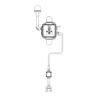
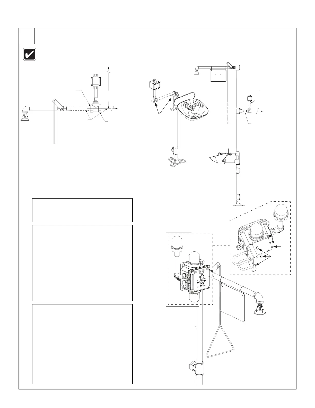
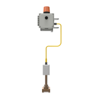
Install the Flow Switch and Mount Signaling Assembly
The flow switch will attach to the mounted alarm via a 6, 12 or 50 foot waterproof cable.
Keep the location for mounting the alarm in mind when choosing the flow switch location.
A
Choose a location for mounting the
flow switch in a horizontal run of the
water supply line.
B
Mount the flow switch assembly in
the water supply line.
• The switch body must be in the
vertical position with the water
pipe horizontal.
• The water flow must be in the
direction marked by the arrow on
the flow switch body.
• Use teflon tape or pipe sealant
(supplied by installer) on all water
pipe connections.
C
Choose a location for mounting the
alarm. For best visibility, the signaling
system should be mounted at least 7'
above ground level.
• The signaling system may be
mounted directly to the drench
shower piping using the supplied
U-bolts and nuts.
• The signaling system can also be
bolted to a flat surface such as
a wall (hardware for this type of
installation is NOT supplied).
Signaling
Assembly
(4x)
(4x)
(4x)
(4x)
16" (406mm)
min. ceiling
clearance
To 1" Water
Supply
Flow Switch
1¼" to 1"
Reducing
Bushing
required
Piping supplied by
installer (must be
minimum 6 inches
from any fittings)
Flow Switch
optional location
(recommended
location for brass
flow switch is
inside of wall)
To 1¼" Water
Supply
Clearances Needed
Recommended Location
for Flow Switch
Piping supplied
by installer
(must be
minimum 6
inches from any
fittings)
Flow Switch
1/2" Piping
supplied by
installer (must be a
minimum 3 inches
from any fittings)