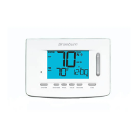
8
9
Rc Rh G
Remove
Factory Installed
Jumper
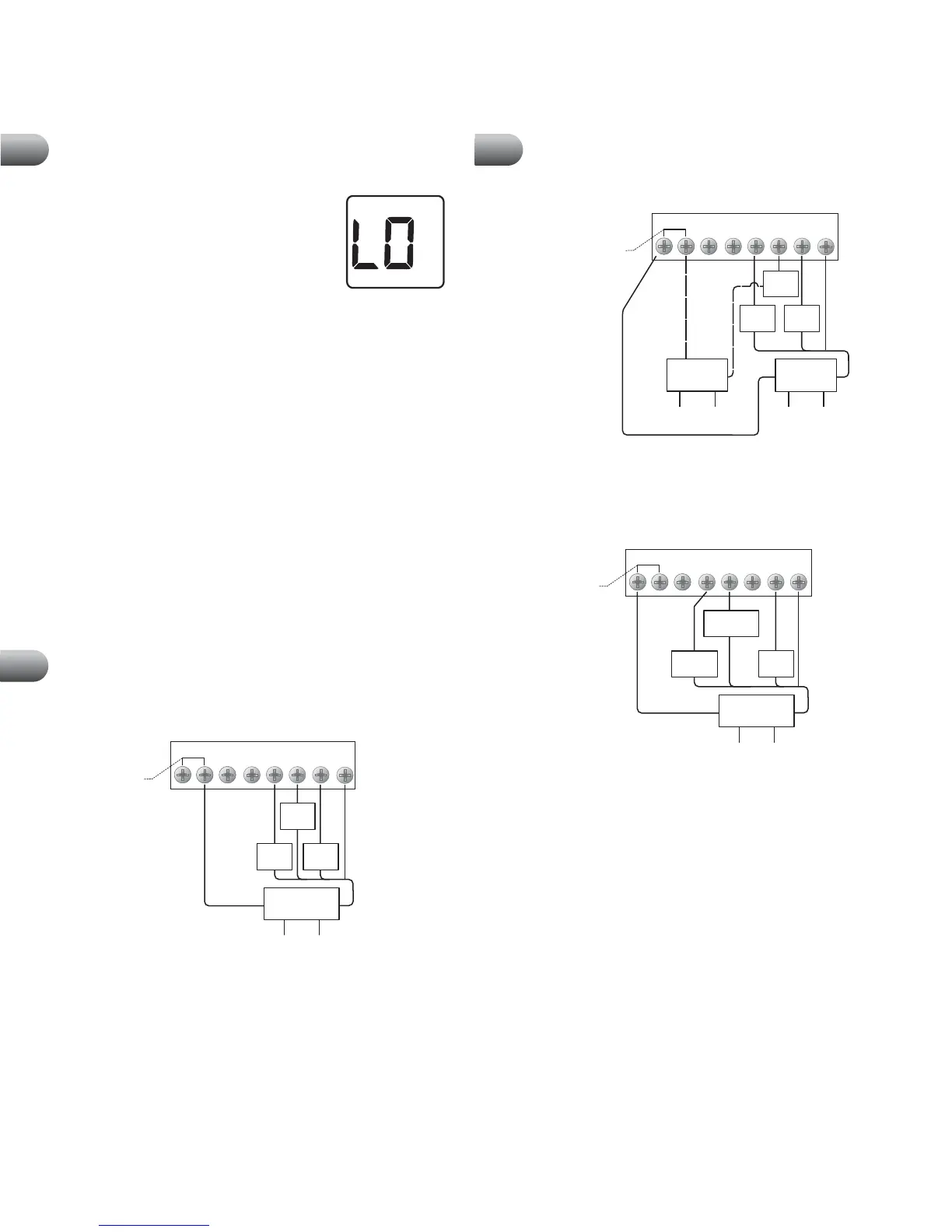
MODEL 1000, 1000NC: Single Stage Conventional Systems (Dual Transformer)
WYB O
Fan
Control
Cool
Control
Cool 24 VAC
Transformer
Heat 24 VAC
Transformer
120
Volt AC
120
Volt AC
Hot Side
Heat
Transformer
Hot Side
Cool
Transformer
Heat
Control
Rc Rh G
Factory Installed
Jumper
MODEL 1000, 1000NC: Single Stage Heat Pump System
W
YB O
Fan
Control
Compressor
Control
Reversing
Valve
24 Volt AC
Transformer
120
Volt AC
Hot Side
Transformer
cont.
cont.
NOTES: 1. Transformer common not required for battery-only
operation of thermostat. 2. For reversing valve active in heating
use B terminal instead of O terminal.
Troubleshooting
6
Symptom: LO is shown in the thermostat display.
Potential Solution: The temperature sensed by the thermostat
is lower than the 40˚ F (4˚ C) lower limit of the thermostat’s
display range. The display will return to normal after the sensed
temperature rises within the 40˚ to 99˚ F (4˚ to 37˚ C) display
range. Turn on the heating system to raise the temperature as
needed for comfort within the room.
This condition could occur from the system being turned off during a cold weather
period or upon installation when the thermostat has been stored for a long period of
time in a cold vehicle or location prior to being installed. The thermostat should be
allowed to warm up prior to installation to allow proper heating control once installed.
Symptom: Cannot program a set point temperature higher than 90˚ F (32˚ C).
Potential Solution: This is above the normal thermostat temperature setting range of
45˚ to 90˚ F (7˚ to 32˚ C).
Symptom: Cannot program a set point temperature lower than 45˚ F (7˚ C).
Potential Solution: This is below the normal thermostat temperature setting range of
45˚ to 90˚ F (7˚ to 32˚ C).
Symptom: Fan continues to run whether the system is on or off.
Potential Solution: Check that the fan control switch is in the AUTO position. This will
allow the fan to run only when the heating or cooling system is turned on and running.
Check thermostat wiring to make sure that the fan control wiring is connected to the
correct terminals on the wiring block. See Section 7.
Symptom: The room is too warm or too cold.
Potential Solution: See Section 5. Review current set point and change as necessary.
Wiring Diagrams
Rc Rh
G
Factory Installed
Jumper
MODEL 1000, 1000NC: Single Stage Conventional Systems (Single Transformer)
WYB O
Heat
Control
Fan
Control
Cool
Control
24 Volt AC
Transformer
120
Volt AC
Hot Side
Transformer
NOTES: 1. Transformer common not required for battery-only operation of
thermostat. 2. For heating or cooling only system, ignore opposite connection.
3. For 2-wire 24 Volt AC or 250 mV - 750 mV millivolt heating systems, ignore
cooling connection and fan control.
C
Transformer Common
(See NOTE 1)
Wiring Diagrams
7
C
Transformer Common
(See NOTE)
NOTE: Transformer common not required for battery-only operation of thermostat.
C
Transformer Common
(See NOTE 1)
7