Do you have a question about the Brainchild P41 and is the answer not in the manual?
Provides an overview of the Fuzzy Logic plus PID profiling controller series and its features.
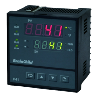
Details the layout and components of the controller's front panel, including displays and buttons.
Illustrates the sequence of key presses for navigating modes and parameters.
Lists and describes various parameters, their addresses, ranges, default values, and data types.
Guides through the process of unpacking the unit and preparing for panel mounting.
Provides diagrams showing the required panel cutout and overall dimensions for P41 and P91.
Outlines essential safety and procedural guidelines for wiring the controller.
Shows the wiring diagrams for rear terminal connections for both P41 and P91 models.
Illustrates the correct methods for connecting power supply and sensor inputs to the controller.
Details wiring for Output 1, covering relay, Triac (SSR), pulsed voltage, linear current, and linear voltage types.
Details wiring for Output 2, covering relay, Triac (SSR), pulsed voltage, linear current, and linear voltage types.
Shows how to wire alarm and event outputs to external devices, including diagrams for load and contactor connections.
Illustrates wiring for event inputs and retransmission outputs, used for sending process or setpoint values.
Explains RS-485 communication interfaces and provides wiring diagrams.
Details RS-232 communication wiring and the configuration of a standard RS-232 cable.
Describes the parameters for data security, including password and code settings.
Details how to select sensor types, input units, decimal points, and scale values.
Explains how to configure the event input for various functions like RUN, HOLD, or ABORT.
Outlines the configuration of different control modes (Heat/Cool, ON-OFF, PID) for the outputs.
Describes the setup for up to three alarm outputs and their functions (process, deviation, band alarms).
Allows users to customize the display by selecting and arranging parameters for the home page.
Guides users through the process of calibrating the unit for improved accuracy.
Explains how to use the digital filter to stabilize unstable process values.
Details how the controller handles failures like sensor breaks or A-D converter issues.
Describes the process of automatically tuning PID parameters for optimal control.
Explains how to manually adjust PID parameters when auto-tuning is insufficient.
Allows direct manual control of heating or cooling outputs by adjusting percentage values.
Covers Modbus RTU protocol, RS-485/RS-232 interfaces, and communication settings.
Explains how to configure outputs for retransmitting process or setpoint values.
Details how to scale linear outputs and retransmission signals based on electrical output ranges.
Introduces the concept of set point profilers for varying process values over time using ramp and dwell segments.
Illustrates combinations of ramp and dwell segments for creating profiles.
Explains the different operating modes of the profiler (Run, Hold, Static, etc.) and their indications.
Describes how to start, pause, resume, and terminate profile execution using the controller's keys.
Explains how to monitor and adjust profile parameters like segment number and time during operation.
Details how to specify the starting point (PV, SP1, STSP) for a profile for smooth operation.
Explains the holdback feature to freeze profiles when process values deviate from set points, with adjustable band and type.
Describes how the profiler behaves and recovers after a power interruption based on the PFR parameter setting.
Guides through the setup of global, profile, and segment parameters for creating profiles according to requirements.
Details the steps for creating and managing profiles using the controller interface, including setting profile numbers and segment data.
Explains how event outputs and PID parameter sets are configured and selected.
Presents a system diagram and explanation for using the controller in a heat treatment oven with multiple heaters and fan control.
Lists power requirements, input resolution, sampling rate, and maximum ratings for various input signals.
Details sensor lead resistance effects, burn-out current, and methods for detecting sensor breaks.
Provides accuracy and impedance details for different sensor types including Thermocouple, RTD, mA, and Voltage.
Details characteristics for relay, pulsed voltage, linear outputs, and their load capacities.
Outlines characteristics for DC voltage supplies, alarm relay ratings, and alarm functions.
Outlines Modbus communication parameters (RS-232/RS-485) and analog retransmission details.
Covers display type, keypad functions, communication ports, and available control modes (ON-OFF, P/PD, PID).
Details the digital filter function and profiler capabilities like number of profiles and segments.
Lists operating temperature, humidity, dimensions, weight, and compliance standards like UL, CSA, and EMC.
Lists available Modbus functions (03, 06, 16) and their corresponding query/response message formats.
Explains how the controller responds to errors or invalid Modbus messages, including exception codes and causes.
Refers to parameter descriptions, error codes, program codes, and explains the 2's complement number system.
Provides practical examples of Modbus queries for reading data, performing resets, entering modes, and modifying calibration.
Lists the necessary calibrators, test equipment, and software for performing manual calibration.
Provides step-by-step instructions for performing manual calibration for thermocouple and RTD inputs using specific signals.
Lists common error codes, their descriptions, and recommended corrective actions for troubleshooting.
Outlines the terms and conditions of the product warranty, including coverage and limitations.
Explains the procedure for returning products, emphasizing the need for a Return Material Authorization (RMA) form.
| Power Supply | 24 VDC |
|---|---|
| Communication | RS-485, Ethernet |
| Operating Voltage | 24 VDC |
| Analog Input Pins | 8 |
| Communication Interfaces | RS-485, Ethernet |