4-24 100-214-276 Rev. 3
Chapter 4: Installation and Setup
Installation Steps
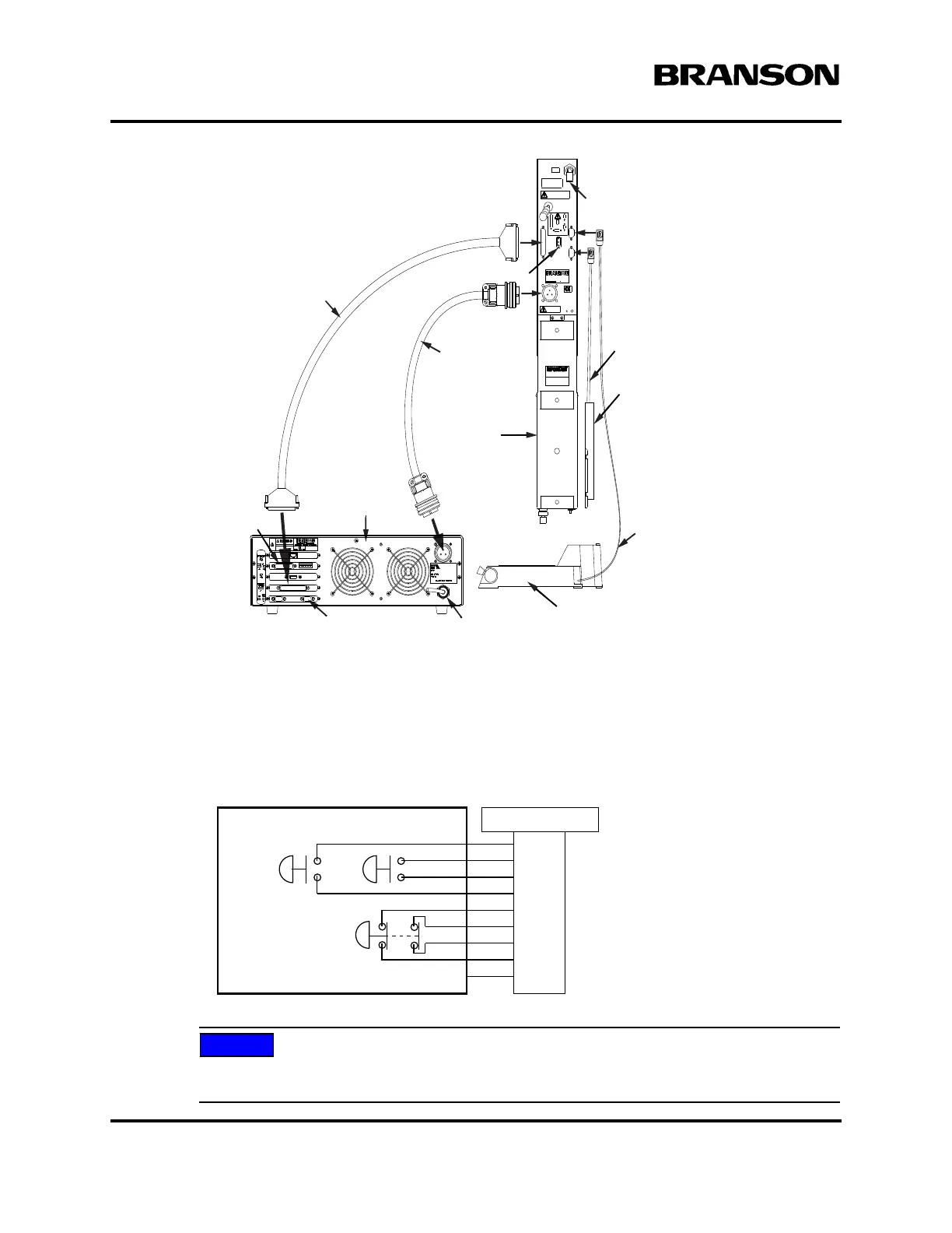
Figure 4.16 Electrical Connections from Power Supply to a 2000X-series Actuator
4.5.8 Start Switch Connection (Automation)
A Branson actuator requires two start switches and emergency stop connection. Stands on a base include
this connection (factory installed and connected from the base) while the stand on a hub and actuator (alone)
applications require the user make their own start switch/E-stop connections, as follows:
Figure 4.17 Start Switch Connection Codes
Solid state devices may be used in lieu of mechanical start switches providing their leakage
current does not exceed 0.1mA.
Actuator
Interface Cable
MPS/GDS
Linear Encoder
Cable**
J931s
RF Cable
Alarm I/O,
Optional
Power Supply
rear view
RS 232 for Host Computer Line Cord
Actuator
Base, shown rotated 90° CCW
Start Switch
Cable
Linear Encoder**
Air Inlet*
*ae/aed actuator air input shown
**aed and aef only
P69
EMER
STOP
START SWITCHES
PB1PB2
1
2
3
4
5
6
7
PB2RTN
9
8
Color Codes
PB1RTN
PB1SRC
PB2SRC
ESTOPSRC
ESTOPSRC
ESTOPRTN
ESTOPRTN
N/C
Blue
Black
White
Orange
Purple
Yellow
Red
Green
Brown
DOC EXPIRES 12PM 7/24/2012. Article or Material must comply with the requirements
stipulated by RoHS in its current version