

L
Larry LarsenAug 2, 2025
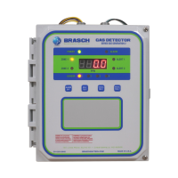
How to fix 'No Active Sensors – 9999' error on Brasch GSE Generation 2?
- SStephen MartinAug 2, 2025
This error occurs when all sensors are set as inactive. To fix this, ensure that at least one sensor is set to active at SW3 on the control board and that it is properly connected.