To replace a remote sensor board assembly, disconnect any power sources from the sensor
board. Remove the four retaining screws in the cover and set the cover aside. Unplug any
connections to the sensor board and remove the four screws securing the sensor board to the
housing. Place the old sensor board aside. After making sure that all jumpers and switches
on the new sensor board match the old sensor board, place the new sensor board into the
housing. Replace the four screws to secure the sensor board to the housing and return and
connections to their original locations. Carefully replace the cover, making sure to align the
indicator LEDs. Firmly tighten the four cover retaining screws. Restore the sensor power
sources and check for proper operation.
Suggested Repair Parts
This Brasch Gas Detector contains few field serviceable parts. However, the fuses are
replaceable in the field. While an open fuse may indicate problems with the circuitry, fuses
may also open because of power surges or ventilation component failure. Therefore, Brasch
recommends that the following fuses be available for replacement.
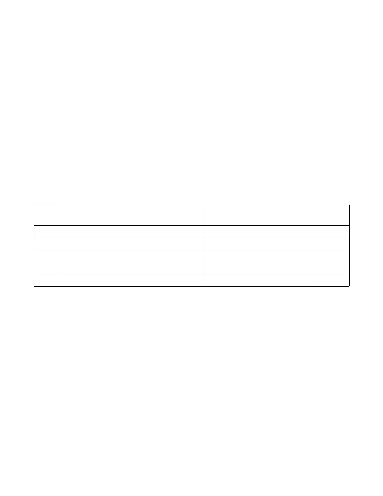
Qty Description Location
Part
Number
6 Fuse, TR5, time-lag, 5.0 A, 250 VAC Relay Fuses TR5-5.0
1 Fuse, TR5, time-lag, 0.400 A, 250 VAC Main Fuse for 120 VAC Units TR5-0.400
1 Fuse, TR5, time-lag, 2.0 A, 250 VAC Main Fuse for 24 VAC Units TR5-2.0
1 Fuse, TR5, time-lag, 0.250 A, 250 VAC Sensor Board Negative Fuse TR5-0.250
1 Fuse, TR5, time-lag, 1.0 A, 250 VAC Sensor Board Positive Fuse TR5-1.0
A package containing the proper quantities of fuses can be purchased through your Brasch
distributor.
IOM01
Rev 1.0 – December 22, 2020 32