Page 76
T
M
U
NFO
LD
(O
UT)
FOL
D
(
IN
)
D
O
W
N
U
P
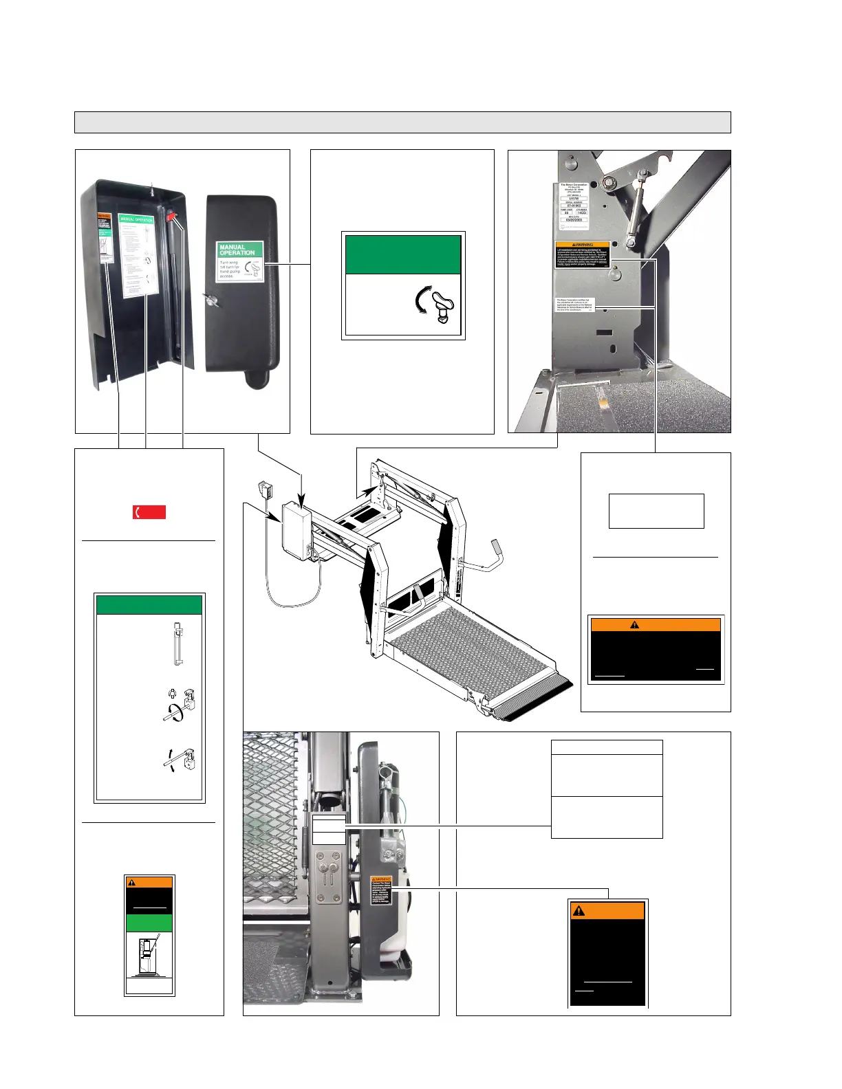
Lift-Posted Decals
Decals and Antiskid
Manual Instructions,
Hand Pump
Decal 29082
Actual Size: 4-1/2" Wide x 8-1/2" Tall
The Braun Corporation certifies that
this wheelchair lift conforms to all
applicable requirements of the National
Standards for School Buses in effect at
the time of its manufacture.
24668
NSSB Lift Certification
Decal 24668
Actual Size:
2-3/4" W. x 1" T.
Microswitch
Adjustment
Instructions
Decal 24490
Actual Size:
2-1/4" Wide
x
2" Tall
Installation and Service
Manual Policy Warning
Decal 25675
Actual Size:
4" Wide x 2" Tall
Warning, Relief
Valve Adjustment
Decal 22249
Actual Size:
1-5/8" Wide
x
2-1/4" Tall
Removal Instruction,
Pump Cover
Decal 29051
Actual Size:
2-1/2" Wide x 2-1/4" Tall
MANUAL
OPERATION
Turn wing
1/4 turn for
hand pump
access.
29051
Lock
Unlock
MANUAL OPERATION
29082
TO REMOVE PUMP HANDLE:
1. Rotate top clip.
Using hand pump handle:
TO UNFOLD PLATFORM (OUT):
1. Close hand pump valve
(turn clockwise).
2. Insert handle in pump and
stroke until platform folds
fully (stops).
3. Open hand pump valve (turn
counterclockwise) until
platform reaches floor level.
Open 1/2 turn only.
4. Close hand pump valve
(turn clockwise).
DOWN (TO LOWER):
Open hand pump valve (turn
counterclockwise). Open
1/2 turn only.
UP (TO RAISE):
1. Close hand pump valve
(turn clockwise).
2. Insert handle in pump and
stroke until platform reaches
floor level.
TO FOLD PLATFORM (IN):
Insert handle in pump and stroke.
Note: Close valve before operating
electric pump.
TO STORE PUMP HANDLE:
1. Insert bottom of handle
behind bottom clip.
2. Rotate clip to lock.
O
P
E
N
C
L
O
S
E
OPEN
VALVE
CLOSE
UNLOCK
LOCK
Actual Size: 1-5/16" Wide x 5/8" Tall
Actual Size: 2-1/16" Wide x 5" Tall
W
A
RNING
Adjust switch as specified
in installation/service
manual.
HYDRAULIC
PRESSURE SWITCH
ADJUSTMENT
Improper hydraulic
pressure switch
adjustment may result
in serious bodily injury
and/or property damage.
27154
Removal, Installation,
Pump Handle
Decal 29052
Hydraulic Pressure
Switch Adjustment
Decal 27154
Microswitch Adjustment Instructions
Unfold/Down (Outside) Microswitch
Turn adjustment bolt clockwise to stop
platform unfold function sooner. Turn
adjustment bolt counterclockwise to allow
platform to unfold further.
Up/Fold (Inside) Microswitch
Turn adjustment bolt counterclockwise
to stop platform raise function sooner.
Turn adjustment bolt clockwise to allow
platform to raise further.
24490
W
A
RNING
Contact The Braun
Corporation before
adjusting hydraulic
pressure relief
valve. Failure to
do so may result
in serious bodily
injury and/or
property damage.
22249
W
A
RNING
Lift installation and servicing prohibited by
anyone who has not been certified by The Braun
Corporation Sales and Service School. Certified
service technicians should call 1-800-THE LIFT
to receive applicable installation/service manual.
Failure to follow this policy may result in serious
bodily injury and/or property damage.
25675
29052
 Loading...