All information herein is proprietary and confidential and may not be copied or reproduced without the expressed written consent of BRAY INTERNATIONAL, Inc.
The technical data herein is for general information only. Product suitability should be based solely upon customer’s detailed knowledge and experience with their
application.
6A O & M : 40
All information herein is proprietary and confidential and may not be copied or reproduced without the expressed written consent of BRAY INTERNATIONAL, Inc.
The technical data herein is for general information only. Product suitability should be based solely upon customer’s detailed knowledge and experience with their
application.
Series 6A Operation & Maintenance – Dimensional Drawings
6A O & M : 40
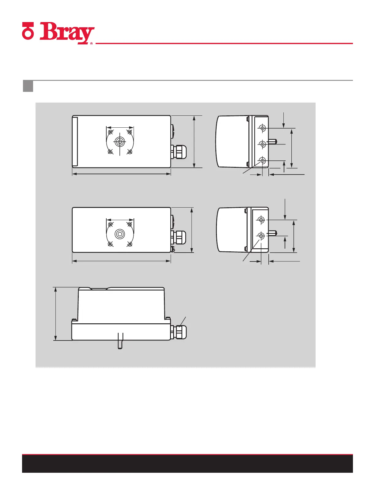
DIMENSIONAL DRAWINGS
Dimensional drawings
Makrolon and stainless steel enclosure double acting (top), aluminum enclosure single acting (center),
Makrolon and aluminum enclosure (bottom), dimensions in mm (inch)
Flameproof enclosure dimensions in mm (inch)
All air connections
All air connections
G 1/4 or 1/4 NPT
G 1/4 or 1/4 NPT
Stainless steel version, values:
1) 74 (2.91)
2) 99 (3.89)
3) 98 (3.86)
4) Dimension at electrical
connection ½-14 NPT (with
adapter) 203 mm
M20 x 1.5
11.2 (0.44)
11.2 (0.44)
185 (7.28)
50 x 4 (1.97 x 0.16) x M6
50 x 4 (1.97 x 0.16) x M6
1)
2)
4)
185 (7.28)
4)
95 (3.74)
3)
96.6 (3.80)
84 (3.31)
29.5
(1.16)
29.5
(1.16)
29.5
(1.16)
72 (2.83)
59 (2.32)
M8, 14 (0.55) deep (4x)
M6, 11 (0.43) deep (4x)
all air connections
G1/4 or 1/4-NPT
1) Connection Y2 only for double-action version
M6, 8 (0.31) deep (2x)
M20x1,5, M25x1,5 or
1/2-NPT (2x)
1)
E
Y1
10.25 (0.4)19.25 (0.36)
34
(1.34)
4.5 (1.8)
25
(0.98)
129.5 (5.1)
14.3
(0.56)
235.3 (9.26)
3.5 (0.14)
5
(0.2)
Ø8 (7)
h9
7 (0.28)
82.5 (3.25)
Ø136.5 (5.37)
158.5 (6.24)
12 (0.47)
7.5
(0.3)
33.5
(1.32)
33.5
(1.32)
25.7
(1.01)
87.2 (3.43)
60 (2.36)
23 (0.91)
65 (2.65)
43 (1.69)
7.75 (0.3)
Ø50 (1.97)
Note: Drawings are shown in first angle