All information herein is proprietary and confidential and may not be copied or reproduced without the expressed written consent of BRAY INTERNATIONAL, Inc.
The technical data herein is for general information only. Product suitability should be based solely upon customer’s detailed knowledge and experience with their
application.
Series 6A Installation, Operation & Maintenance
Installable Options
6A O & M : 20
FACTORY OR FIELD INSTALLABLE OPTIONS
The S6A comes standard with guides beneath the mother-
board so that optional modules can be added.
Tools Needed:
• T2O Torx
• Phillips Screwdriver
Step A
To install any of the optional modules proceed as follows:
1. Disconnect electrical power from the supply to the
positioner
2. Remove pressure from the pneumatic supply lines to the
positioner.
3. Remove the positioner cover by loosening the 4 screws
using the Phillips screwdriver.
4. Remove the module cover by loosening the 2 screws using
the T20 torx drive.
Note: Step A must be performed before installing any of
the modules.
Installing the Feedback Module (Iy Module)
Feedback Module (ly Module)
Function
The optional Iy module indicates the current actuator posi-
tion as a dual line signal with Iy = 4 to 20 mA. The Iy module
is potentially isolated from the standard controller. Due to the
dynamic control, this module can report the arising opera-
tional faults automatically.
Device features
The Iy module is:
• Single channel
• Potentially isolated from the standard controller.
Note: The current actuator position is indicated only after
a successful initialization of the positioner. [Refer to the
“Calibration and Commissioning” section]
Proceed as follows to install the optional Iy module:
1. Perform Step A to remove the module cover
2. Slide the Iy module up to the end stop in the lower stack
of the module rack.
3. Connect the module to the motherboard. For this purpose,
use the 6-pole flat ribbon cable provided.
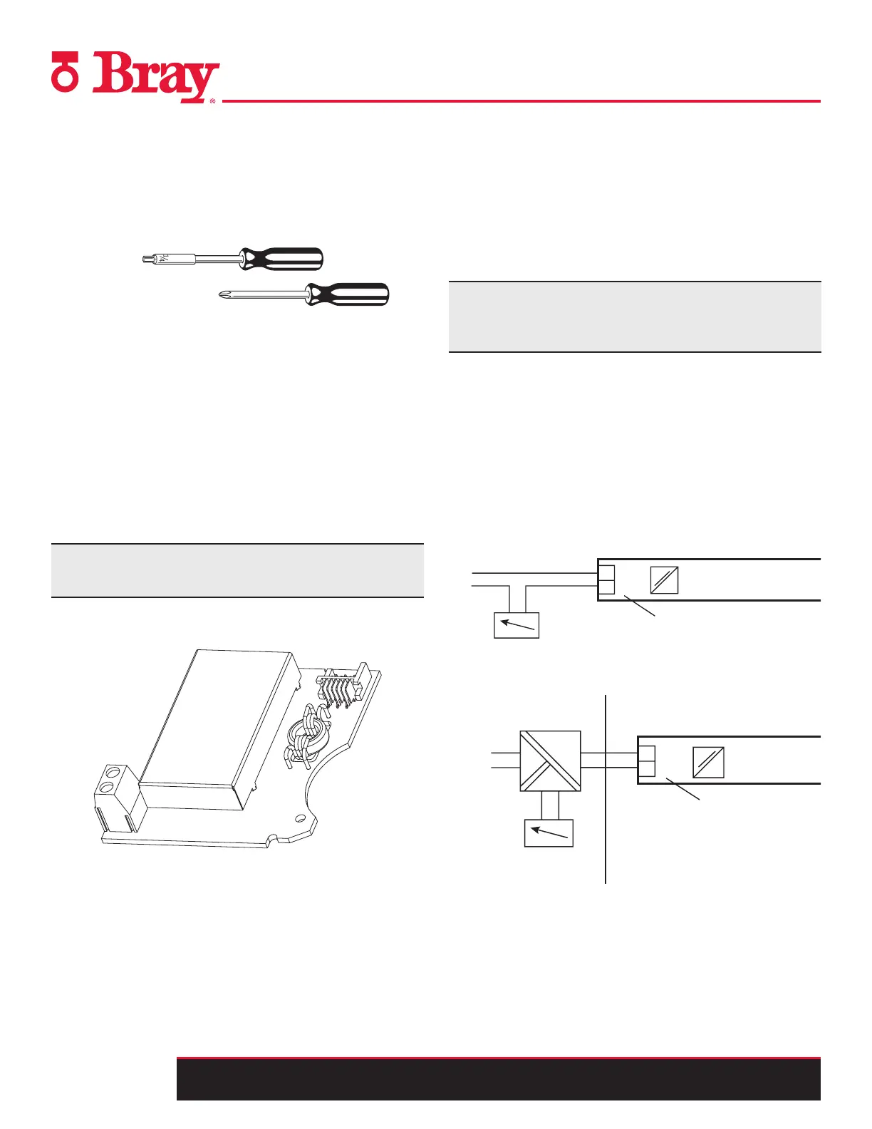
4. Refer to Figure 8 and Figure 9 to connect the Iy module in
standard and intrinsically safe applications.
≤ 30 V
E
U
H
Iy module
6DR4004-6J
Non-hazardous area
Intrinsically safe
power source
Hazardous area, Zone 1 or zone 2
EEx
++
I
+
I
U
Ammeter
Figure 8.- Iy module 6DR4004-8J, not Ex
61
62
≤ 35 V
+
E
I
I
y module
6DR4004-8J
Iy module 6DR4004-8J, not Ex
+
UH
Current Meter
(Ammeter)
Figure 9. - Iy module 6DR4004-6J, EEx i

 Loading...

