All information herein is proprietary and confidential and may not be copied or reproduced without the expressed written consent of BRAY INTERNATIONAL, Inc.
The technical data herein is for general information only. Product suitability should be based solely upon customer’s detailed knowledge and experience with their
application.
Series 6A Installation, Operation & Maintenance
Installable Options
6A O & M : 21
Installing the Mechanical Limit Switch Module
Mechanical Limit Switch Module
Function
This module is used to report two limits. These two limit
switches are voltage free and rated for 4A at 24V DC or AC
250V.
Device features
The mechanical limit switch module consists of:
• One binary output to display a collective fault message.
Compare with the device features of the alarm unit.
• Two switches to report two mechanically adjustable limits.
Both of these switches are electrically independent from the
remaining electronic unit.
Note: Only qualified personnel should be allowed to install
and connect the Mechanical Limit switch module
Proceed as follows to install the mechanical limit switch
module:
1. Perform Step A to remove the module cover
2. Disengage the motherboard by carefully bending the four
brackets.
3. Insert the mechanical limit switch module from the top
up to the upper printed circuit board guide of the mod-
ule rack.
4. Slide the mechanical limit switch module unit into the
printed circuit board of the module rack approximately
1
/8"
towards the right.
5. Screw in the special screw through the mechanical limit
switch module into the positioner shaft. Tighten the spe-
cial screw with a torque of 17.7 in-lbs.
NOTICE
A pin in the actuating disc bearing is pressed. Align this pin
before it touches the special screw. You must rotate the
actuating disc bearing and the special screw simultaneously
so that the pin is inserted into the special screw.
An insulating cover is provided over the mechanical limit
switch module. Place the insulating cover to one side under
the motherboard seat on the container wall. The recesses of
the insulating cover must fit in the corresponding webs of the
container wall.
6. Place the insulating cover on the mechanical limit switch
module by bending the container walls carefully.
7. Engage the motherboard into the four brackets.
8. Connect the motherboard and the optional modules to
the ribbon cables provided.
9. Connect the motherboard and the potentiometer to the
potentiometer cable.
10. Using both the screws, fasten the module cover provided.
Do not use the standard module cover.
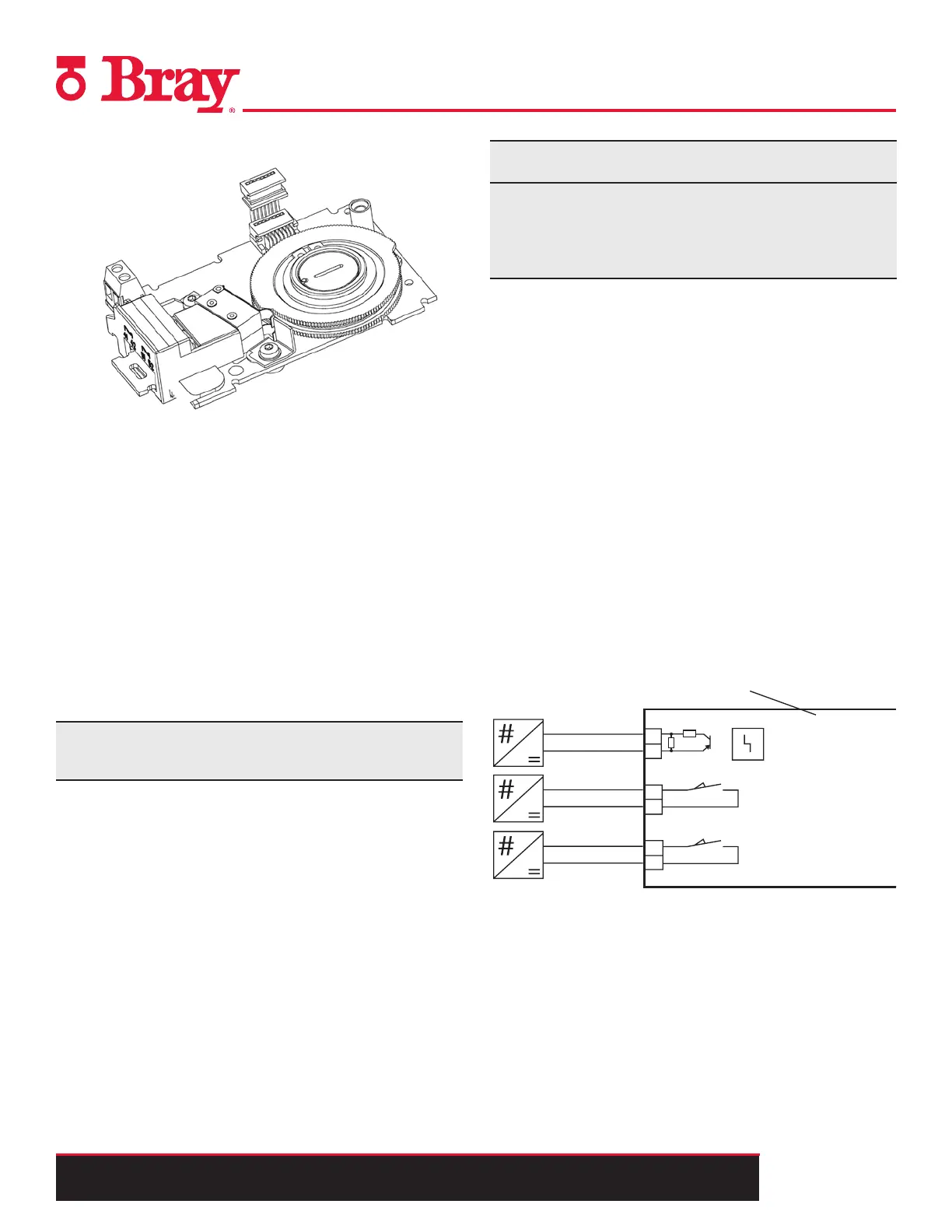
11. Refer to Figures 10 and 11 to connect the Mechanical
Limit switch module in standard and intrinsically safe
applications.
31
32
41
42
51
52
<35 V
24 V DC
max. AC 250V
4A AC/DC
24 V DC
max. AC 250V
4A AC/DC
1K21
10K
Fault message
Limit value A1
Limit value A2
+
+
+
Mechanical limit switch
module 6DR4004-8K
Figure 10. - Mechanical limit switch module 6DR4004-8K, not Ex

 Loading...

