All information herein is proprietary and confidential and may not be copied or reproduced without the expressed written consent of BRAY INTERNATIONAL, Inc.
The technical data herein is for general information only. Product suitability should be based solely upon customer’s detailed knowledge and experience with their
application.
Series 6A Installation, Operation & Maintenance
Installable Options
6A O & M : 22
31
32
41
42
51
52
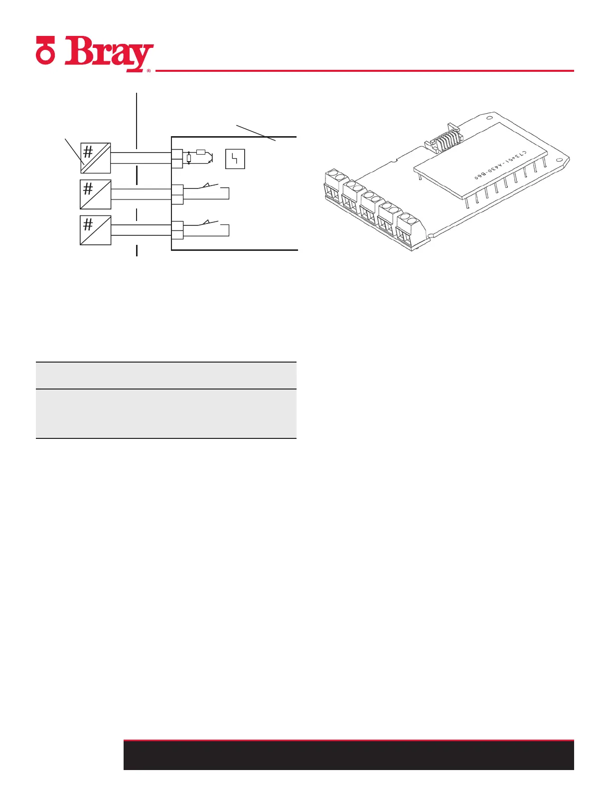
max. DC 8,2 V
Umax. DC 30 V
Umax. DC 30 V
Imax 100 mA
Imax 100 mA
Mechanical limit switch
module 6DR4004-6K
Fault message
Limit value A1
Limit value A2
2K1
10K
Intrinsically safe
switching amplifier
to DIN EN 60947-5-6
Non Hazardous Area Hazardous Area, Zone 1
EEx
=
=
+
+
+
Connect the mechanical limit switch module as follows:
1. Loosen the screw on the transparent cover
2. Pull the transparent cover up to the front end stop.
3. Tighten every cable in the corresponding terminal.
NOTICE
Verify the electrical specifications for these terminals based
on the wiring diagram. Do not use the non Ex board in a
hazardous environment.
4. Slide the transparent cover up to the end stop of the
motherboard.
5. Tighten the screw on the transparent cover
6. Connect the cables of each switch to the lug of the printed
circuit board in pairs. Use the provided cable tie for this
purpose.
Installing the Alarm Module
Alarm Unit
Function
The alarm unit triggers fault messages and alarms using binary
outputs. The message function is based on the change in the
signal status:
If the signal status is “HIGH”, there is no alarm message and
the binary inputs are conductive.
If the signal status is “LOW”, the module reports an alarm by
shutting down binary outputs using a high-resistance.
Due to the dynamic control, this module can report the aris-
ing operational faults automatically. Set parameters 44 to 51
to activate and parameterize the output of alarms and fault
messages. Apart from binary outputs, the alarm unit has a
double-acting binary input BE2. Depending on the selected
parameters, it is used to block or to move the actuator it to
its end position. Configure the suitable settings on param-
eter 43.
Device features
The alarm unit has the following features:
Available in two versions.
• Explosion-proof version for connecting to a switching
amplifier in conformity with EN 60947-5-6.
• Non-explosion-proof version for connecting to power
sources having a maximum of 35 V.
Three binary outputs. Binary inputs are potentially isolated
from the standard controller and from each other. The binary
input has dual functionality. Both inputs are implemented as
logical OR combination.
• Isolated for voltage level
• Not isolated for dry contacts
Figure 11. - Mechanical limit switch module 6DR4004-6K, EEx i

 Loading...

