All information herein is proprietary and confidential and may not be copied or reproduced without the expressed written consent of BRAY INTERNATIONAL, Inc.
The technical data herein is for general information only. Product suitability should be based solely upon customer’s detailed knowledge and experience with their
application.
Series 6A Installation, Operation & Maintenance
Installable Options
6A O & M : 23
Proceed as follows to install the alarm unit:
1. Perform Step A to remove the module cover
2. Slide the alarm unit below the motherboard in the module
rack. Ensure that you slide it up to the end stop.
3. Connect the module to the motherboard. For this purpose,
use the 8-pole flat ribbon cable provided.
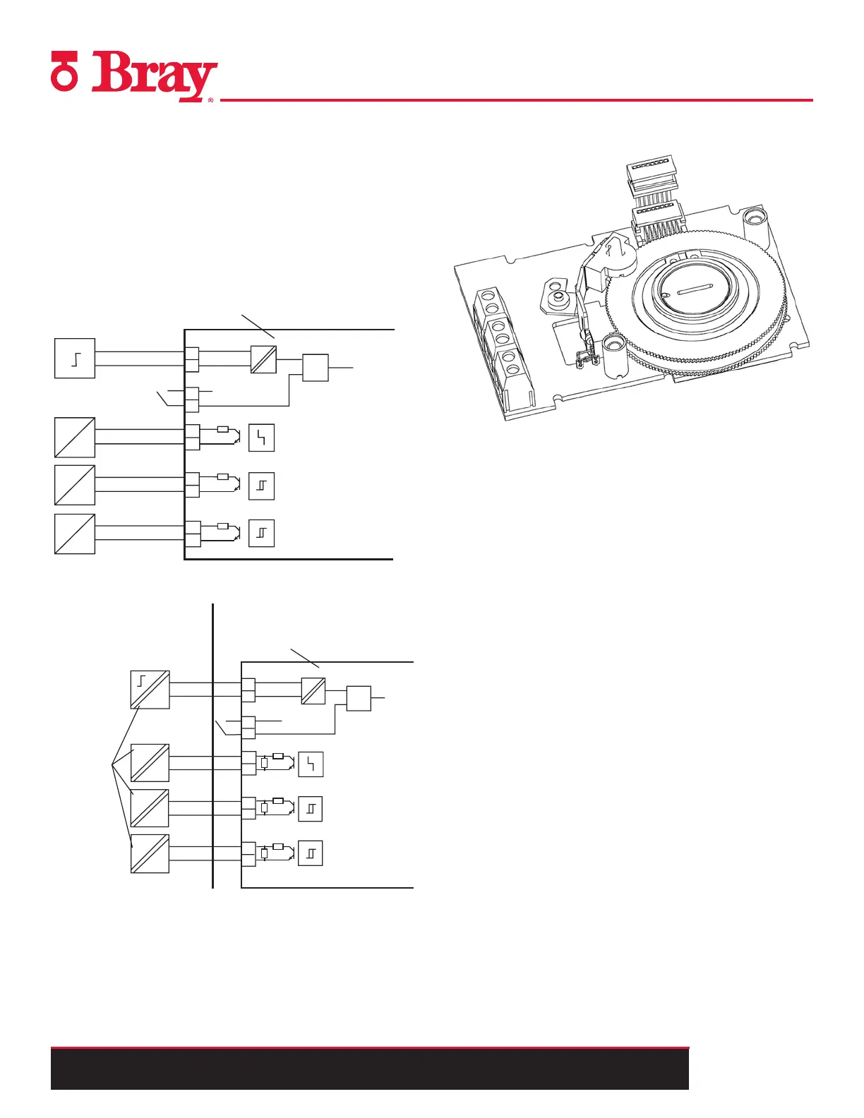
4. Refer to Figures 12 and 13 to connect the Alarm unit in
standard and intrinsically safe applications
11
12
21
22
31
32
41
42
51
52
≤ 30 V
35 V
35 V
35 V
6DR4004-8A
+
+
+
+
Digital input 2
1K
1K
1K
+ 3 V
≥ 1
Fault message
Limit value A1
Limit value A2
#
#
#
#
11
12
21
22
31
32
≤ 25,2 V
8,2 V
8,2 V
8,2 V
Fault message
Limit value A1
Limit value A2
Alarm module
6DR4004-6A
Digital
input 2
Intrinsically safe
switching
amplifier to DIN
EN 60947-5-6
Non-hazardous area Hazardous area, zone 1 or zone 2
EEx
EEx
EEx
EEx
+
+
+
+
+ 3 V
41
42
51
52
≥ 1
2K1
10K
2K1
10K
2K1
10K
#
#
#
#
Installing the Slotted Initiator Alarm Unit
Slotted Initiator Alarm Unit
Function
If the standard controller requires electrically independent
limit value messages, the slotted initiator alarm unit is used
instead of the standard alarm unit.
A binary output is used to display a collective fault message.
Compare with the function of the alarm unit. The floating
binary output is implemented as an automatic fault indicating
semiconductor output.
The other two binary outputs are used for the message of two
limits L1 and L2 which can be adjusted mechanically using
slotted initiators. Both these binary outputs are electrically
independent from the remaining electronic unit.
Device features
The slotted initiator alarm unit, abbreviated as SIA unit con-
sists of three binary outputs.
Proceed as follows to install the SIA unit:
1. Perform Step A to remove the module cover
2. Unscrew both the screws on the motherboard.
3. Disengage the motherboard by carefully bending the four
brackets.
4. Insert the SIA unit from the top up to the upper printed cir-
cuit board guide of the module rack.
5. Slide the SIA unit in the printed circuit board of the mod-
ule rack approximately
1
/8" to the right.
6. Screw in the special screw through the SIA unit into the
positioner shaft. Tighten the special screw with a torque
of 17.7 in-lbs.
Figure 12. - Alarm unit 6DR4004-8A, not Ex
Figure 13.
- Alarm unit 6DR4004-6A, EEx i

 Loading...

