5
Series 71 – Electric Actuator
Installation, Operation and Maintenance Manual
ELECTRICAL OPERATION
The motors used in the Bray Series are of either permanent split capacitor
(PSC) design for single phase line applications or permanent magnet (PM)
design for ACDC power Travel limit switches are mechanical form
(SPDT) with contact rated at A VAC
The PSC motor is designed for impedance protection such that the current
and self-heating will be limited in cases where the torque capacity of
the unit is exceeded to the point where the motor stalls The PM motor
controllers implement self-resetting over-current protection which will also
limit the current and torque capacity of the motor
MECHANICAL OPERATION
Mechanically the ratio of the gearing determines the output speed of
the unit The actuator utilizes high efficiency spur gears Positioning is
determined by an indicatorcam shaft which is linked to the output shaft In
the declutched position the manual override drives the output
7.0 ACTUATION
MANUAL OPERATION
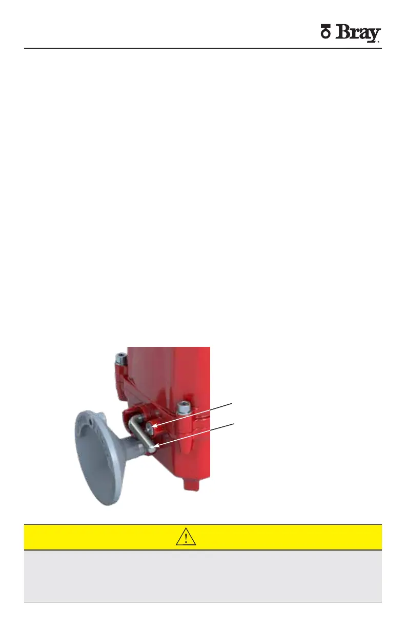
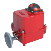
The Bray Series actuators are provided with a declutchable manual
override system To manually operate the actuator push in the manual
override button and rotate the declutchable lever counter-clockwise until it
reaches the o’clock position Once the declutchable lever is in position
turn the handwheel until the valve reaches the required position The motor
does not shutoff during manual operation and will continue to rotate the
upper gearing if being commanded by the process Push in the manual
override button and rotate the declutchable lever clockwise until it reaches
the o’clock position to re-engage the upper gearing and motor drive
Manual Override Button
Manual Override Lever
REMOTE OPERATION
CAUTION
Verify that the main electric power supplied to the actuator is in compliance with
the specifications on the actuator label
Engaging the handwheel before or during the application of a supply voltage will
prevent the actuator motor from driving the valve to the position commanded by
the process


 To Next Page