6
Series 71 – Electric Actuator
Installation, Operation and Maintenance Manual
S VAC ONOFF ACTUATOR WITH INTERPOSING RELAY BOARD
The back feeding of one actuator by another one wired in parallel is
eliminated by using the S IRB If the actuator is running Open and the
customer switches “instantaneously” to run Closed the Open relay will take
time to “drop-out” and the Close relay will take time to “pull-in” This time
lapse is ~ms The time delay provided by the S IRB will protect the
switches and gears from the controller’s instantaneous command signal
reversal Current draw and field wiring are not affected by the IRB
NOTE The host controller should use a one second time delay for command
signal reversal
CAUTION
Apply voltage to only one direction terminal at a time
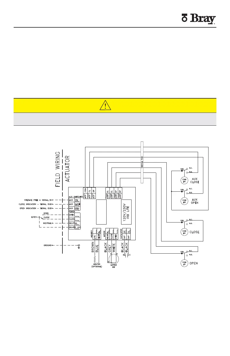
WD-000545
NOTES:
1. HEATER IS OPTIONAL.
2. HEATER LIVE CONNECTION IS REQUIRED WHEN A HEATER IS INSTALLED.
3. AUXILIARY SWITCHES ARE VOLTAGE FREE, RATED FOR 3A, 125/250VAC.
4. AUXILIARY SIGNAL OUT IS SAME VOLTAGE AS AUXILIARY SIGNAL IN.
5. LIVE, NEUTRAL, & GROUND ARE A SINGLE PHASE POWER SUPPLY.
6. ALL SWITCHES SHOWN IN DEACTIVATED STATE.
FIELD TERMINALS
· 14-24 AWG MAX RANGE, 18 AWG RECOMMENDED
· PUSH BUTTON CLAMP
· 105 °C, 300V MIN RATED WIRE
· STRIP WIRE: .39"-.43" [10-11mm]
· GROUND WIRE GAUGE TO BE EQUAL TO LARGEST SUPPLY CONDUCTOR.


 To Next Page