8
All information herein is proprietary and condential and may not be copied or reproduced without the expressed written consent of BRAY INTERNATIONAL, Inc.
The technical data herein is for general information only. Product suitability should be based solely upon customer’s detailed knowledge and experience with their application.
Series 92-93 Pneumatic Actuator
Operations and Maintenance Instructions
WARNING
Some actuators may have spring cartridges installed.
Before disassembly, all spring cartridges must be
placed into the relaxed (fully extended) position. All
compressed air must be removed from inside the actuator
(See warning on previous page) and the actuator pinion
must be allowed to rotate so the springs may be relaxed.
Care must be taken to verify that any device connected
to the actuator, such as a valve mounted underneath,
is not preventing the movement of the springs to the
relaxed position.
If the actuator is installed on a valve, remove the actuator
from the valve, and move the actuator to a clean work
area. Remove the indicator pointer. Remove both end
caps by loosening the hex head end cap bolts. Remove
both pistons by rotating the pinion counter-clockwise
until the piston heads are protruding from the body.
Pull the pistons out. Using snap-ring pliers, remove the
pinion retaining ring and acetal washer, then remove
the pinion from the body. The pinion bearings, o-rings,
cam and spacer may then be removed.
Adding Spring Cartridges
WARNING
Before disassembly of the actuator, the pneumatic
air supply must be completely disconnected from
the actuator, and all compressed air stored within the
actuator must be released. Auxiliary devices connected
to the actuator, such as tubing, ball valves, solenoid
air valves, valve positioners, etc. can block the release
of air from within the actuator. Do not rely upon the
features or controls of any auxiliary device to release
the air from inside the actuator to render it safe for
disassembly.
Move the pinion to the fully closed (0°) position. Remove
the end caps and insert the desired number of spring
cartridges into the end cap pockets, up to a maximum
of six cartridges per end cap.
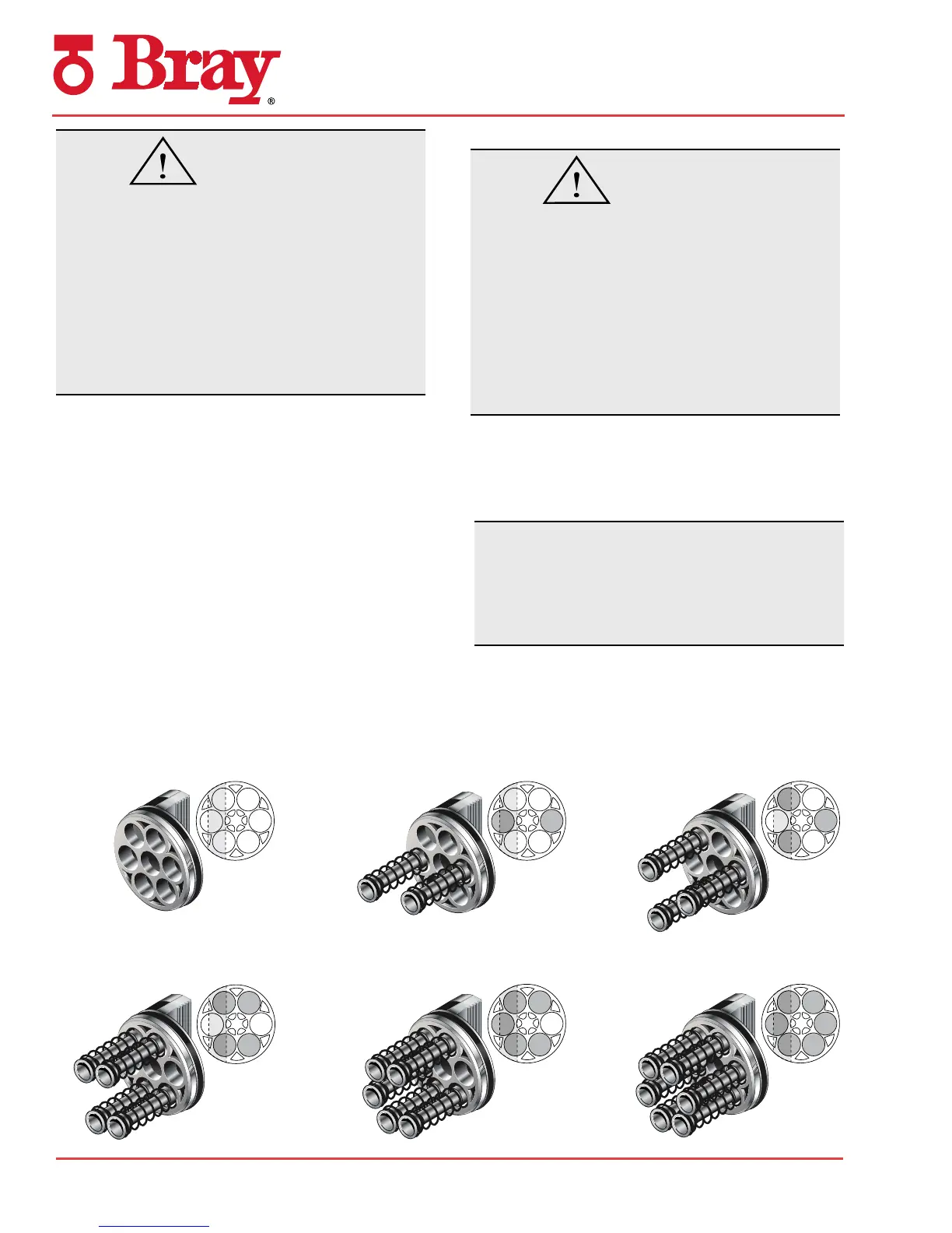
NOTICE
For proper operation, actuators equipped with Spring
Cartridges should have the spring cartridges installed
in accordance with the positions shown in gure 2.
Align the end cap with the body so the spring cartridges
t into the piston pockets. Attach the end caps to the
body with the hex head end cap bolts. Tighten the bolts
gradually in a diagonal sequence.
Proceed to Final Assembly and Testing.
XX = SIZE CODE
2 SPRINGS
EACH PISTON
3 SPRINGS
EACH PISTON
4 SPRINGS
EACH PISTON
5 SPRINGS
EACH PISTON
6 SPRINGS
EACH PISTON
XX
XX
XX
Figure 2

 Loading...

