2
All information herein is proprietary and condential and may not be copied or reproduced without the expressed written consent of BRAY INTERNATIONAL, Inc.
The technical data herein is for general information only. Product suitability should be based solely upon customer’s detailed knowledge and experience with their application.
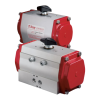
Series 92-93 Pneumatic Actuator
Operations and Maintenance Instructions
Description of Operation
The Bray Series 92/93 Pneumatic Actuators feature a
double piston, rack and pinion mechanism designed to
automate quarter-turn valves. In the Series 92 Double-
Acting Actuator, pressure introduced through Port A
(the left port when facing the ports) forces the pistons
away from each other and causes the pinion to rotate
in a counter-clockwise direction. Pressure introduced
through Port B (the right port when facing the ports)
is directed through an internal passage to the opposite
side of the pistons, which forces the pistons together and
rotates the pinion in a clockwise direction. Normally,
the clockwise rotation (pistons moving together) closes
the attached valve, and the counter-clockwise rotation
(pistons moving apart) opens the attached valve.
In the Series 93 Spring-Return Actuators, spring cartridges
have been added to push the pistons together by spring
force in the event the compressed air pressure being lost.
This spring force normally closes the attached valve.
However, in the event that the valve is required to open
under spring force, refer to the fail open portion of the
Installation section.
Operating Medium
NOTICE
The recommended operating medium is clean, dry
industrial compressed air, 40 - 140 psig (3 - 10 bar.)
An air line lubricator is suggested for fast cycling ap-
plications, i.e. more than 10 cycles per minute. Other
media such as hydraulic oil, water, or certain other
inert gases may also be used in some instances, but the
factory should be consulted for specic applications.
Operating Temperature
NOTICE
The recommended operating temperature range is -20°F
to 200°F (-29°C to 95°C). Below 32°F (0°C) care must
be taken to prevent condensed moisture from freez-
ing in the air supply lines. Consider the use of an air
dryer if the device is installed in a cold location. The
air dryer must be capable of lowering the dew point of
the air to a temperature 36°F (20 °C) lower than that
of the surrounding environment. The air dryer must be
properly maintained and kept in operation.
Installation
Bray Series 92/93 Actuators are designed to mount
directly on the top plate of Bray Valves. Before the
actuator is mounted on a valve, it is a good practice
to lubricate the output bore of the actuator with thick
grease. The grease will make it easier to remove the
actuator from the valve stem, even after years of service.
Normally, the actuator is mounted with its long side
parallel to the pipeline*. A double acting actuator will
normally rotate the valve stem clockwise to close, and
counter-clockwise to open. Spring return actuators
will normally rotate the valve stem clockwise to close
with the spring stroke, and counter-clockwise to open
with the air stroke. The normal operation of the spring
cartridges is therefore fail closed.
Direction of operation may be changed to fail open
by any one of several different methods. Refer to the
Assembly Instructions and Exploded View in Figure 3
on page 11 for more details.
Fail Open Assemblies
If the actuator is attached to a valve, the buttery valve
disc is shipped in the full open position (as no air
pressure is present to compress the springs and close
the valve disc.) The sealing surface, or disc edge, is
therefore exposed. Damage to that surface will cause
premature seat failure.
NOTE: Consult a factory representative when a non-
standard actuator conguration is made in the eld
or is being changed in the eld. Example: Mounting
an actuator perpendicular to the pipe due to space
restrictions on site.
CAUTION
Use caution installing the valve being careful not to
damage the disc edge. It is recommended to:
• Remove the actuator. Be sure to scribe the valve
and actuator to ensure the re-installed actuator is
in the exact same quadrant as originally congured
• Install the valve per the attached installation tag
instructions
• Re-install the actuator ensuring it is in the proper
quadrant

 Loading...