4
All information herein is proprietary and condential and may not be copied or reproduced without the expressed written consent of BRAY INTERNATIONAL, Inc.
The technical data herein is for general information only. Product suitability should be based solely upon customer’s detailed knowledge and experience with their application.
Series 92-93 Pneumatic Actuator
Operations and Maintenance Instructions
Fail Closed Assemblies
If the actuator is attached to a valve, the buttery valve
is shipped in the full closed position (as no air pressure
is present to compress the springs and open the disc).
CAUTION
Installing the valve with the disc in the full closed
position may create a compression set on the seat
causing higher than expected torques or premature
seat failure. It is recommended to:
• Remove the actuator. Be sure to scribe the valve
and actuator to ensure the re-installed actuator is
in the exact same quadrant as originally cong-
ured
• Install the valve per the attached installation tag
instructions
• Re-install the actuator ensuring it is in the
proper quadrant
Mounting the Actuator to the Valve
The actuator is attached to the valve by means of the
studs and nuts furnished in the mounting kit. Thread
the studs into the proper holes in the actuator, before
installing the actuator on the valve. The studs should be
snug in the bottom of the tapped holes; there is no need
to torque them. Install the actuator on the valve making
sure that the base of the actuator ts at against the valve
mounting ange. Use the nuts and washers from the kit
to complete the installation. Torque the nuts in a diagonal
pattern to assure equal loading of the studs.
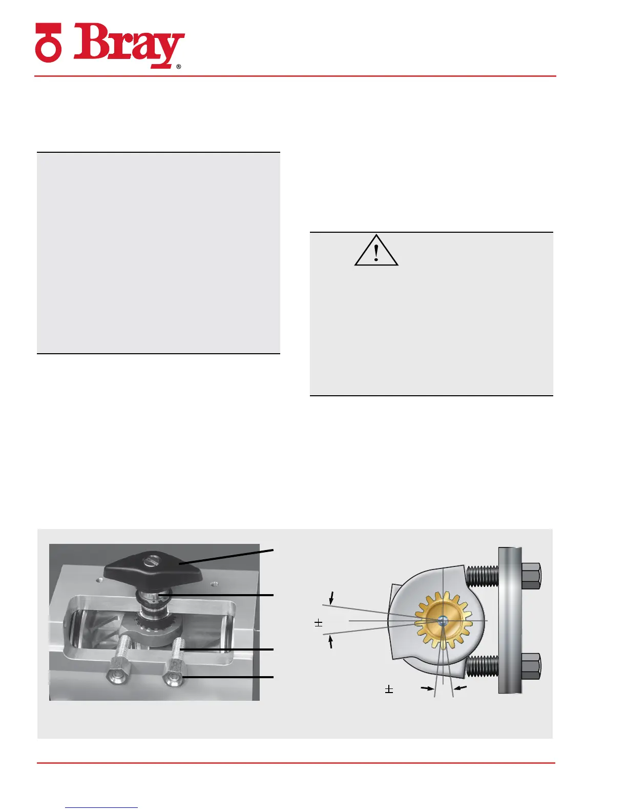
Setting the Travel Stops
The nal step in the installation process is to check the
travel stop settings. The travel stops are set for 90° of
travel at the factory; however, each installation is differ-
ent so they should be checked before putting the valve
in service. The actuators are designed with a nominal 5°
over or under travel at each end of rotation. A screwdriver,
an open end or box end wrench and a hex wrench, of the
appropriate size, are the only tools required to make the
necessary adjustments. Refer to Figure 1 below.
WARNING
Before setting the travel stops, the pneumatic air supply
must be completely disconnected from the actuator,
and all compressed air stored within the actuator must
be released. Auxiliary devices connected to the actua-
tor, such as tubing, ball valves, solenoid air valves,
valve positioners, etc. can block the release of air from
within the actuator. Do not rely upon the features or
controls of any auxiliary device to release the air from
inside the actuator to render it safe for disassembly.
Remove the black Position Indicator Pointer (23) to expose
the wrench ats on the top of the Pinion (3).
Rotate the valve to the desired position by using a
wrench on the wrench ats on the top of the Pinion (3).
Loosen the Lock Nut (12) on the Travel Stop Screw (13).
It is not necessary to remove the nut completely. Using
the hex wrench, turn the screw in or out until the desired
5°
5°
Figure 1
23
3
13
12

 Loading...

