2
DC(M)24-(44/88) Series - Installation, Operation & Maintenance Manual Continued
Warning - These actuators are designed for use only in conjunction with operating controls. Where an operating control failure would result in personal injury
and/or loss of property, it is the responsibility of the installer to add safety devices or alarm systems that protect against, and/or warn of, control failure.
To avoid excessive wear or drive time on the motor, use a controller and/or software that provides a time-out function to remove the signal at the end
of rotation (stall).
Disclaimer - The performance specifications are nominal and conform to acceptable industry standards. For application at conditions beyond these
specifications, consult the nearest Bray oce. Bray controls shall not be liable for damages resulting from misapplication or misuse of its products.
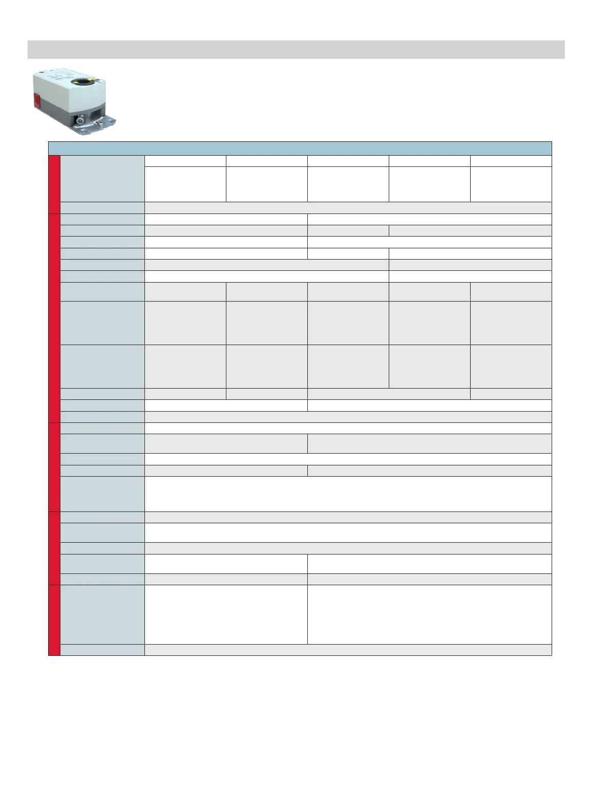
Technical Specifications - DC(M)24-44 Series Actuator
Type
Actuator Models
DC24-44-TP DC24-44-TAP DC24-44-TPTO DCM24-44-P DCM24-44-AP
Non-Spring Return
Floating*
Plenum Cable
Non-Spring Return
Floating*
Plenum Cable
Auxiliary Switches
Non-Spring Return
2-Position/Floating
Plenum Cable
Non-Spring Return
Modulating
Plenum Cable
Non-Spring Return
Modulating
Plenum Cable
Auxiliary Switches
Torque
44 lb-in. (5 Nm)
Electrical
Operating Voltage 24 VAC +20%, -15% at 50/60 Hz 24 VAC/DC +-20%
Power Consumption
2.3 VA 2.0 VA, 1W 2.1 VA, 1.2W
Operational Protection N/A Timeout/Overload Protection
Control Signal Floating 2-Position/Floating 0(2)-10V
Input Impedance
N/A >100k Ohms
Feedback Signal
N/A 0 to 10 V (Maximum Output Current DC 1mA)
Auxiliary Switch Rating
N/A
4A Resistive,
2A Inductive
N/A N/A
4A Resistive,
2A Inductive
Switch Range
(Switch A)
N/A
0 to 90° with 5°
Intervals (Recom-
mended Range Usage
0 to 45°)
Factory Setting 5°
N/A N/A
0 to 90° with 5°
Intervals (Recom-
mended Range Usage
0 to 45°)
Factory Setting 5°
Switch Range
(Switch B)
N/A
0 to 90° with 5°
Intervals (Recom-
mended Rang Usage
45 to 90°)
Factory Setting 85°
N/A N/A
0 to 90° with 5°
Intervals (Recom-
mended Rang Usage
45 to 90°)
Factory Setting 85°
Switching Hysteresis
N/A 2° N/A 2°
Equipment Rating
Class 2 per UL/CSA,Class III per EN60730 Class 2 according to UL, cUL; Class III per EN60730
Electrical Connection
3 ft. (0.9 m) Pre-cabled - AWG 18 - Plenum Rated Cable
Operation
Manual Override
Manual Operation by Selecting Override Knob when Power is o
Runtime for 90°
of Rotation
90 sec. at 60 Hz (108 sec. at 50 Hz) 90 sec.
Rotation Range
Nominal Angle of Rotation 90°, mechanically limited to 95°
Cycle Life
60,000 full strokes/ 1.5 million repositions 100,000 full strokes/ 5 million repositions
Mechanical
Connections
Round Shafts - 3/8 to 5/8 in. (8 to 16 mm) diameter
Square Shafts - 1/4 to 1/2 in. (6 to 12.7 mm)
Hex Shafts - 9/16 in. (15 mm)
Minimum Shaft Length - 3/4 in. (20 mm)
Environmental
Enclosure
NEMA 2, IP54 according to EN60529
Ambient Conditions
(Non-Condensing)
Operating — -25 to 130°F (-32 to 55°C); 0 to 95% RH, non-condensing
Storage — -40 to 158°F (-40 to 70°C); 0 to 95% RH, non-condensing
Audible Noise Rating
35 dBA at 1 m
Dimensions
6.2" L × 2.8" W × 2.4" D
(157mm L × 71mm W × 61mm D)
6.6" L × 2.8" W × 2.4" D
(166.7mm L × 71mm W × 61mm D)
Weight
1.06 lb (0.48 kg) 1.35 lb (0.61 kg)
Conditions
Agency
Certifications
UL listed to UL873-cUL certified to Canadian
Standard C22.2 No. 24-93, CE
In accordance with the directive set forth by
the European Union for Electromagnetic
Compatibility (EMC) 2004/108/EC
Emissions Standards EN61000-6-3
Immunity Standards EN61000-6-2
UL listed to UL60730-cUL certified to Canadian Standard C22.2 No.
24-93, These devices were approved for installation in plenum areas by
Underwriters Laboratories, Inc., per UL 1995 CE listed with EN60730-1,
EN60730-2-14
Warranty
5 Years limited from time of shipment.
* Not eligible for SPST control
 Loading...