4
DC(M)24-(44/88) Series - Installation, Operation & Maintenance Manual Continued
Safety Instructions - Definition of Terms Read, Follow and Save these instructions
WARNING
Personal injury/loss of life may occur if you do not follow a procedure as specified.
CAUTION
Equipment damage or loss of data may occur if you do not follow a procedure as specified.
NOTICE
Used without the safety alert symbol indicates a potential situation which, if not avoided, may result in an
undesirable result or state, including property damage.
WARNING
Do Not Open the Actuator
Qualified Personnel
A qualified person in terms of this document is one
who is familiar with the installation, commissioning
and operation of the device and who has appropriate
qualifications,
such as:
• Is trained in the operation and maintenance of
electric equipment and systems in accordance with
established safety practices.
• Is trained or authorized to energize, de-energize,
ground, tag and lock electrical circuits and equipment
in accordance with established safety practices.
• Is trained in the proper use and care of personal
protective equipment (PPE) in accordance with
established safety practices.
• Is trained in first aid.
• In cases where the device is installed in a potentially
explosive (hazardous) location – is trained in the
operation, commissioning, operation and mainte-
nance of equipment in hazardous locations.
Product Description
The DC(M)24-44/88 Series Actuators are Non-Spring Return Electric Actuators that operate on AC 24V
power, floating control, direct-coupled, actuators.
Required Tools
• 4 mm hex key (included)
• 4 mm (5/32-inch) drill bit and drill
• Small flat-blade screwdriver
• Marker or pencil
NOTE: Place the actuator on the damper shaft so
that the front of the actuator is accessible. The label
is on the front side.
1. Determine whether the damper blades will rotate
clockwise or counterclockwise to open. See Figure 12
and Figure 13.
2. If the blades will rotate counterclockwise, slide the
manual override switch to manual, and move the ad-
justment lever to the right. Return the switch to auto-
matic. See Figure 9.
Mounting Orientation
UL NEMA Type 2 and IP54 approved in all positions
except as shown below:
NOTE:
The DC(44/88) Series Enhanced actuator comes
with a factory-installed 1/2-inch shaft guide. If the
shaft size is 1/2-inch, proceed with Figure 6.
Estimated Installation Time
30 Minutes
Instructions
Mounting and Installation
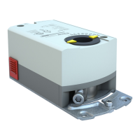
a. Actuator
b. Position indicator
c. Mounting bracket
d. Mounting screws
e. 4 mm hex key
f. Shaft insert for use with
3/8-inch (8-10 mm) shafts
Figure 1. Parts of the DC(M)(44/88) Series Enhanced Rotary Actuator.
Figure 2. Unapproved Position
for UL NEMA Type 2 and IP54.
 Loading...