6
DC(M)24-(44/88) Series - Installation, Operation & Maintenance Manual Continued
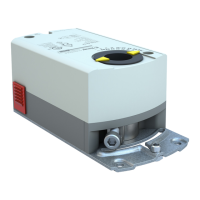
Figure 8. Attaching the Mounting Bracket.
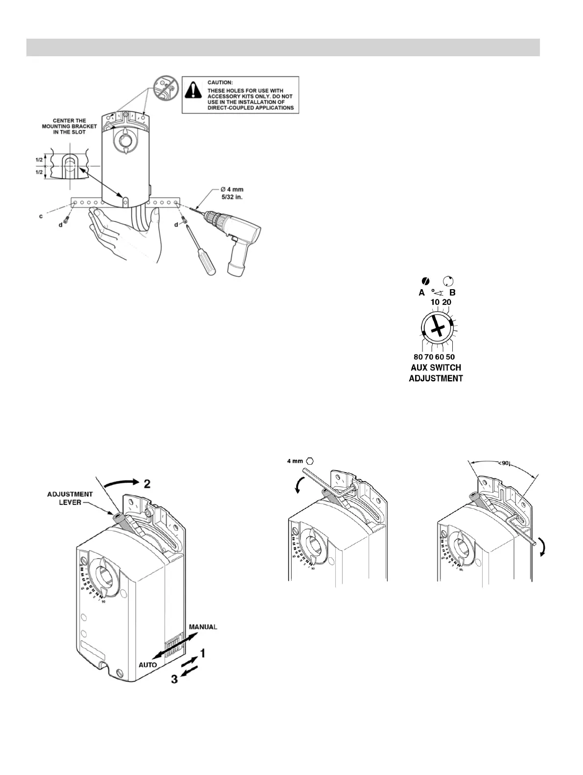
Figure 11. Moving the Mechanical Range Stop.
Figure 10. Auxiliary Switch Setting Dial.
Figure 9. Manual Override.
Manual Override
To move the damper blades and lock the position
with no power present, do the following:
1. Slide the red manual override knob toward the
back of the actuator. See Figure 9.
2. Make adjustments to the damper position.
3. Slide the red manual override knob toward the
front of the actuator.
Once power is restored, the actuator returns to
automated control.
Mechanical Range Adjustment
1 2
Factory setting: A = 5° B = 85°
Use a flat-blade screwdriver to adjust the A switch.
The long arm of the † points to the setting. Manually
turn the red ring of the B switch. The narrower tab on
the ring points to the setting. See Figure 10.
The auxiliary switch setting shafts rotate with the
actuator.
NOTE: The scale is valid only when the actuator is
in the 0 position on clockwise motion.
1. Loosen the stop set screw.
2. Move it along the track to the desired position,
and fasten it in place using maximum 26 to
44 lb-in (3 to 5 Nm) torque.
Dual Auxiliary Switch Setting
For DC24-44-TAP, DCM24-44-AP, DC24-88-TAP,
DCM24-88-AP.