9
DC(M)24-(44/88) Series - Installation, Operation & Maintenance Manual Continued
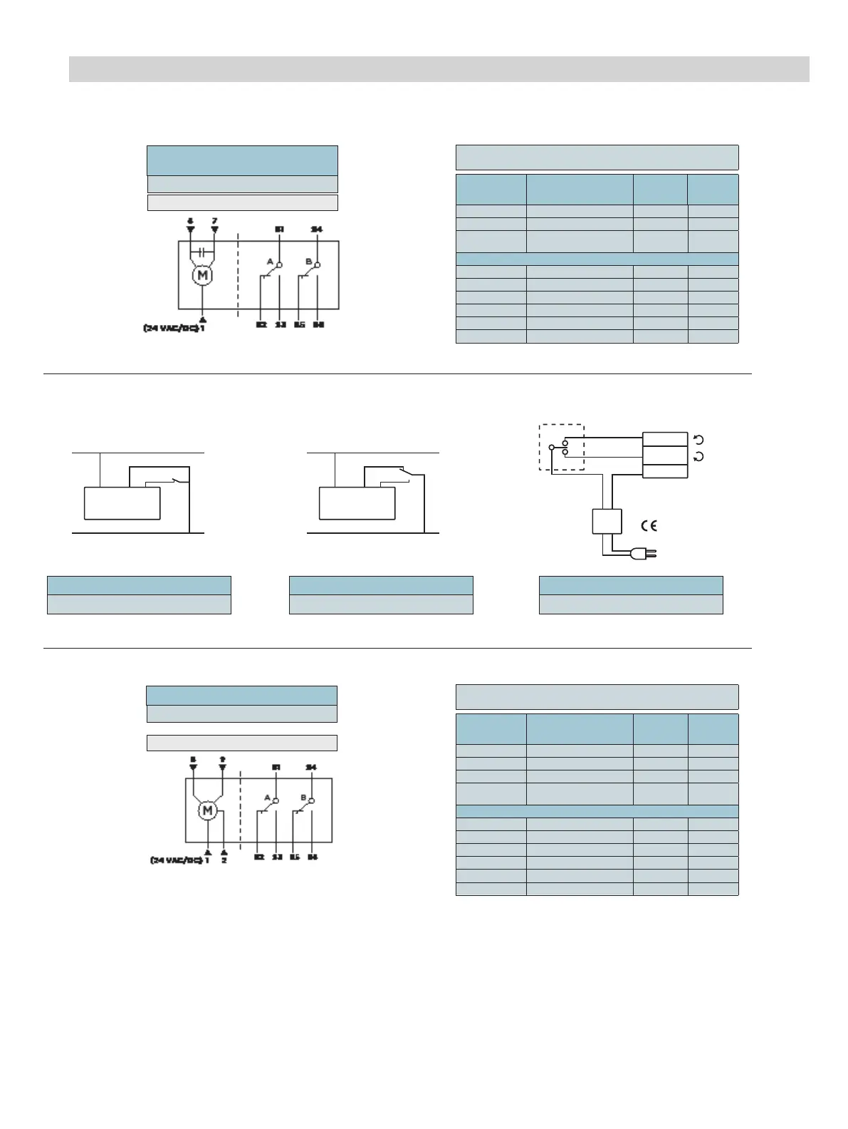
Wiring DC24-88 Series
2-POSITION/FLOATING CONTROL
Standard
Symbol
Function
Terminal
Designa-
tion
Color
1 Supply (SP) G Red
6 Control Signal clockwise Y1 Violet
7
Control Signal
Counterclockwise
Y2 Orange
Factory-Installed Options
S1 Switch A Common Q11 Gray/Red
S2 Switch A N.C. Q12 Gray/Blue
S3 Switch A N.O. Q14 Gray/Pink
S4 Switch B Common Q21 Black/Red
S5 Switch B N.C. Q22 Black/Blue
S6 Switch B N.O. Q24 Black/Pink
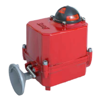
MODULATING CONTROL
Standard
Symbol
Function
Terminal
Designa-
tion
Color
1 Supply (SP) G Red
2 Neutral (SN) G0 Black
8 0(2) to 10V input signal Y Gray
9
Output for 0-10V
position indication
U Pink
Factory-Installed Options
S1 Switch A – Common Q11 Gray/Red
S2 Switch A – N.C. Q12 Gray/Blue
S3 Switch A – N.O. Q14 Gray/Pink
S4 Switch B – Common Q21 Black/Red
S5 Switch B – N.C. Q22 Black/Blue
S6 Switch B – N.O. Q24 Black/Pink
Warning - These actuators are designed for use only in conjunction with operating controls. Where an operating control failure would result in personal injury and/or loss of property, it is the
responsibility of the installer to add safety devices or alarm systems that protect against, and/or warn of, control failure.
To avoid excessive wear or drive time on the motor, use a controller and/or software that provides a time-out function to remove the signal at the end of rotation (stall).
Disclaimer - The performance specifications are nominal and conform to acceptable industry standards. For application at conditions beyond these specifications, consult the nearest Bray oce.
Bray controls shall not be liable for damages resulting from misapplication or misuse of its products.
Mixed switch operation is not permitted. To the switching outputs of both auxiliary switches (A and B), only apply: UL/CSA: Class 2 voltage.
CE: Separated Extra-Low Voltage (SELV) or Protective Extra Low Voltage (PELV), according to HD384-4-41.
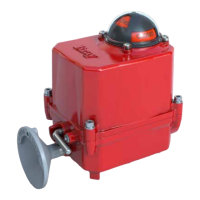
DC24-88-TP
DC24-88-TAP
PLENUM CABLE
DCM24-88-(A)P
PLENUM CABLE
2-Position/Floating Control
Modulating
G Y1 Y2
0 VAC/DC
24 VAC/24 VDC
G Y1 Y2
NEUTRAL
24
VAC
EARTH GROUND
ISOLATING CLASS 2
TRANSFORMER FOR
24 VAC POWER
SAFETY ISOLATING
TRANSFORMER
PER EN 60742
7 (ORANGE)
6 (VIOLET)
1 (RED)
0 VAC/DC
24 VAC/24 VDC
CONTROL METHOD
2-Position, SPST
(Single-Pole, Single-Throw)
2-Position, SPDT
(Single-Pole, Double-Throw)
Floating Control
24 VAC/DC