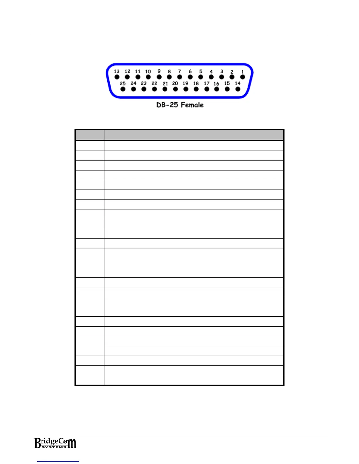
APPENDIX A: ACCESSORY CONNECTOR DESCRIPTION
PIN # Description
1 13.8 Volts out (1A max)
2 Communications Bus – BUSY
3 Communications Bus – DATA
4
5
6
7
8 Discriminator Out – Demodulated received audio
9
10 RSSI – Received Signal Strength Indicator
11 CrossBand Discriminator Out – X-Band Repeater
12
13
14 Rx Module – General Purpose Input 1
15 Rx Module – General Purpose Input 2
16 Rx Module – General Purpose I/O 1 – Fan2/Fan3 Control
17 Rx Module – General Purpose I/O 2 – COS Output
18
19 TX Audio Input
20 External PTT Input
21 TX Subaudible Data or BROADBAND/Composite Input
22 TX Module – General Purpose Input 1
23 Tx Module – Fan2/Fan1 Control
24 Tx Module – General Purpose I/O 2
25 GND
25