ALTAIR 8800 micro Users Manual
© Briel Computers 2010 page 17
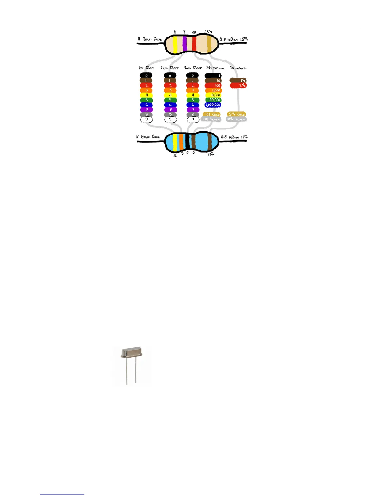
Resistor color chart
The first color on the left is Yellow which equals the value 4. The 2
nd
color is Violet which equals 7. The 3
rd
color is red. This is your multiplier. Red equals 2 so we add 2 zero’s to the end. So, the resistor value is 4-7-00
4700 or 4.7K. The gold band indicates that value will be within 5% of the value when measured.
Find the 3.3K resistor. The 3.3K resistor has the value Orange, Orange, Red, and Gold. Bend the metal wire
tabs at a 90 degree angle at the ceramic edges so the resistor forms a U shape. On the top side of your printed
circuit board (PCB) locate a resistor spot for 3.3K and insert the resistor into the holes and make the resistor sit
flat on the PCB. There is no polarity on the resistor so it does not matter which side gets inserted into which
hole. While holding the resistor flat on the board with one hand, turn over the board and open up the wires so
they point away from each other enough so that the resistor will not fall out. Set the board down on the table
and place your iron tip on one side of the round ring hole and on the wire. Count to 5 then touch the other side
of the hole with solder. Try not to touch the iron. Wait until the solder begins to melt and flow. Make sure you
are only touching the ring and the resistor wire with the iron. Apply enough solder so the wire forms the shape
of a triangle. At this point, remove the solder, then the iron. Check your work to make sure the solder adhered to
the ring only. Now solder the other resistor wire and ring. Cut the extra lead wire off close to the PCB. Repeat
with all the other resistors. I like to keep all my resistors facing the same way so that all the gold rings are on
the same side. It does not make any difference if you do this or not, but try not to unsolder a component unless
you have to. Please note that there is no resistor #15. R15 was removed from the design.
Step 3: Install the Crystals The Crystals are like the heartbeat of a CPU. CPU’s operate on
timing and synchronization. There is one 5MHz for the Propeller CPU (terminal) and one 16MHz crystal for the
ATMEGA8515 CPU (replaces 20MHz). The numbers are clearly labeled on top and they can be installed in
either direction. Like the resistor, install the wire leads until the component sits flush with the board. Hold the
component, turn over the board and separate the 2 leads away from one another to help hold the crystal on the
board. Now set the board down and solder the crystals to the board. Cut the extra lead length off.