ALTAIR 8800 micro Users Manual
© Briel Computers 2010 page 18
Step 4: Install the Diode. The diode is like the resistor in shape but it is polarized. You must install
it so the white stripe on the diode matches the white stripe on the PCB. Bend the leads just like the resistors and
push it flush onto the PCB. Turn over and solder down the leads and cut the extra length off.
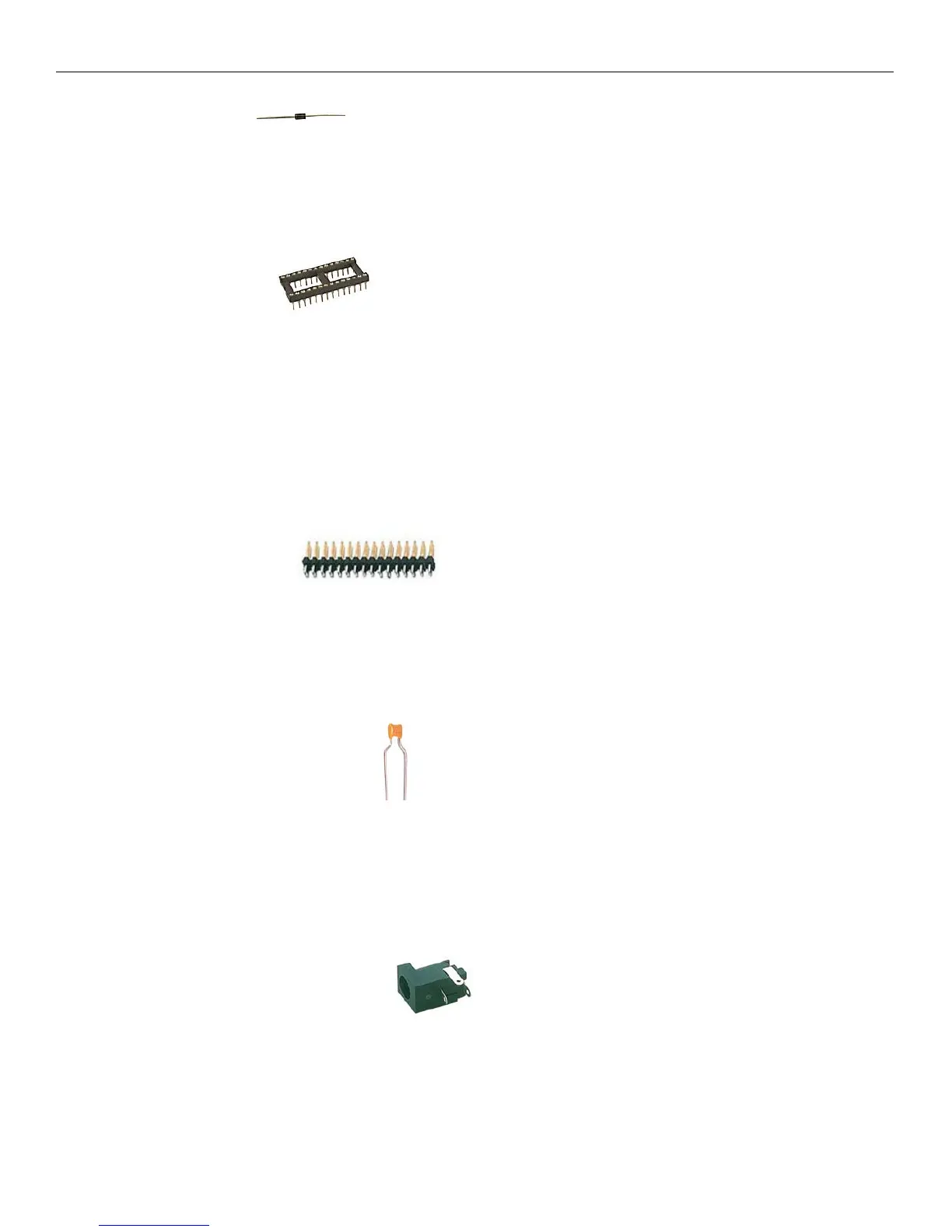
Step 5: Install the Sockets. Sockets are the host spot for the integrated circuits (IC’s). One short
edge will have a notch in it and the white silkscreen on the PCB will have a matching notch. This helps identify
where pin 1 is on the chips. When installing the socket onto the PCB, make sure you match the notch up with
the PCB drawing of the notch. Hold the socket flush on the board and flip the board over. Carefully set the
board down so that the socket remains installed on the board. Solder two opposite corner pins and flip the board
over and make sure that the socket is still flush on the board. If not, you can heat the pin up and push the socket
flush. Solder the rest of the pins down. Repeat for the remaining sockets. Check your work before moving on.
One of the biggest issues with kit building is missed solder spots. Make sure you solder every pin correctly.
Step 6: Install 40 pin headers. There are 3 40 pin IDC .100” spacing headers on the
mainboard. One is used for expansion; the other 2 are for connection to the front panel. The shorter side gets
inserted into the PCB. Make sure it is inserted all the way, hold the connector and flip the board over. Solder
one pin on each edge and check to make sure the header is still flush with the board. Finish soldering the rest of
the pins. Double check all the pins before soldering the next header. There is no polarity on the headers and they
can install in either direction. Just be sure that the longer leads are pointed up.
Step 7: Install the ceramic capacitors. There are 12 .1uF capacitors and 2 of the 22pF capacitors.
Logically, there are 2 that are different from the others and that’s the easiest way to tell the difference. They are
not polarized so you can install them in either direction. You should be able to mount these flush with the board
and then solder them down. Cut the extra length off of the leads after soldering.
Step 8: Install the DC Power Connector. Make sure the hole for the wall wart power supply is
facing the edge of the board. It is easier if you bend the leads away from each other then flip the board over to
solder them down.