ALTAIR 8800 micro Users Manual
© Briel Computers 2010 page 19
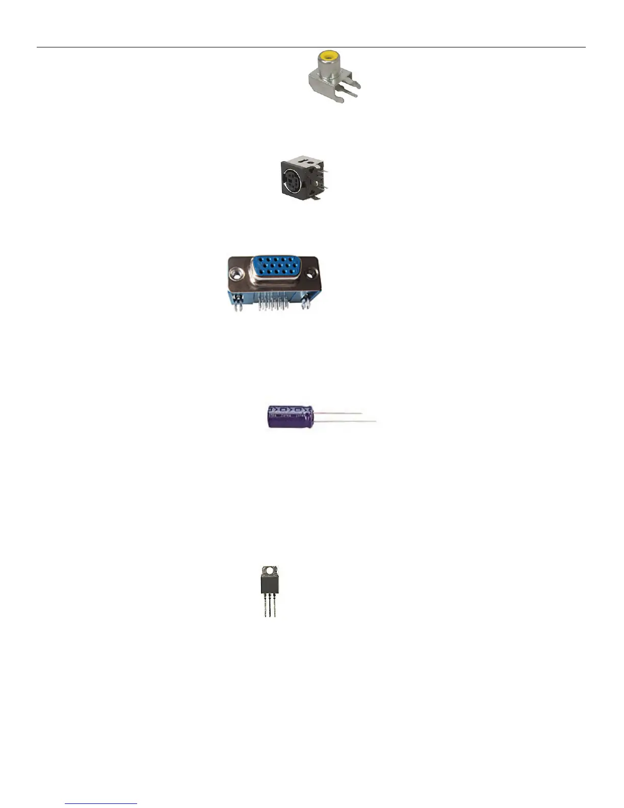
Step 9: Install the Composite Video Out connector. Make sure the yellow post portion is facing
the edge of the board. Mount it flush and bend the leads to hold component in place. Flip the board over and
solder down.
Step 10: Install the PS/2 keyboard connector. When installing the PS/2 connector, take your time
and get all the pins lined up correctly. Make sure the connector is flush with the PCB and flip the board over.
Check to make sure you get all connectors soldered correctly with no solder bridges.
Step 11: Install the VGA connector. This connector fits with ease onto the board. Be sure
to check for bent pins before inserting into the PCB. Flip the board and solder all the leads including the two
large mounting tabs. This will help hold the connector onto the PCB better.
Step 12: Install the Electrolytic Capacitors. These capacitors are polarized and must
be installed in the correct orientation onto the board or you will damage the capacitors and the board. Look at
the large 100uF capacitor and you will see a – (negative) sign on one side with an arrow. That is the negative
lead and is the shorter lead. The other lead is the + (positive) lead and is longer. Insert the capacitor with the
longer lead at the + marked hole on the PCB and push the capacitor flush onto the board. Flip the board over
and solder both leads and cut the extra length away. Repeat for the 2 smaller 10uF capacitors.
Step 13: Install the Voltage regulators. Voltage regulators convert voltage and supply a steady
supply to the IC’s. There are 2 of these and it is important that you do not get these mixed up or damage will
occur to the board. One is labeled 7805. This one is closer to the DC power connector. Install through the 3
holes and then bend the regulator over so that it is laying down flat on the PCB. The hole should match up with
the large hole on the PCB. Place one screw threw the hole and put one nut on the bottom side of the screw. Do
not over tighten the screw. Solder the 3 leads and cut the extra lead lengths off. Repeat for the 3940 voltage
regulator.