4 BRIGGSandSTRATTON.COM
Thank you for purchasing this home standby
accessory. When installed according to these
instructions, the monitoring device will provide years
of dependable service. Keep your purchase receipt
with this instruction sheet and store with your other
generator manuals after installation.
IMPORTANT Illustrations used in this document are
for reference and may not represent the actual unit
being serviced. Your installation will be similar.
Disconnect Power
Before performing any installation, maintenance,
or service on the generator, ALWAYS perform the
following steps:
1. Set generator system switch to OFF.
2. Set generator circuit breaker to OFF.
3. Remove 15 Amp fuse from control panel.
4. Utility voltage is present at generator control
panel. Remove the fuses from the transfer switch to
disconnect power before servicing the control panel.
5. Disconnect negative battery cable from negative
battery terminal, indicated by NEGATIVE, NEG, or (-).
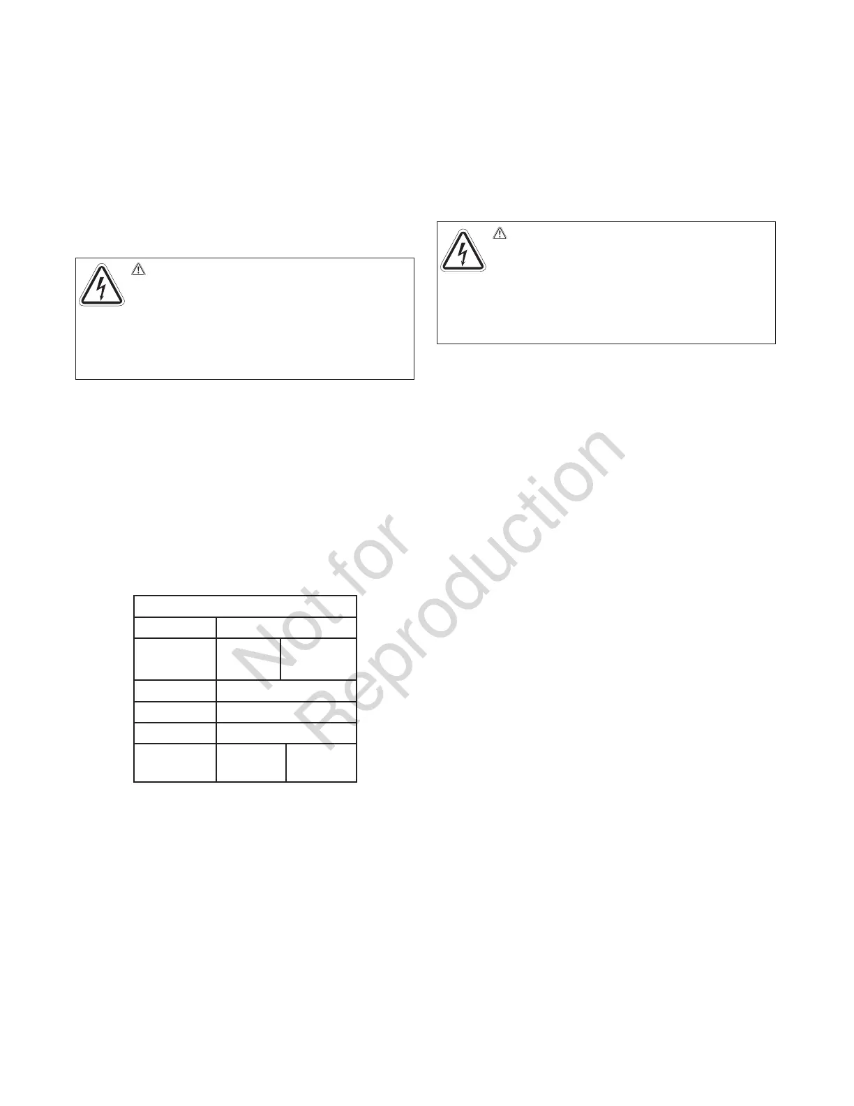
Torque Table
Utility 250 lb-in.
Generator
50 lb-in.
(100A)
250 lb-in.
(150/200A
Neutral 250 lb-in.
Ground 50 lb-in.
Fuse Block 12 lb-in.
Control
12 lb-in.
(J10)
2.5 lb-in.
(J9)
Installation: 6421 Kit
ACCM Upgrade Kit
1. Make sure the generator is in the OFF (0) position.
Remove 15A fuse from generator control panel.
2. Remove utility voltage from transfer switch. Open
the Utility Disconnect Circuit breaker inside the
transfer switch.
3. Remove wire harness from terminal J9 of TRCM
(Trasnferswitch Relay Control Module).
4. Remove TRCM from standoffs.
5. Add two additional standoffs to ACCM board and
replace any damaged standoff.
6. Install ACCM board and plug the wire harness that
came with ACCM board to the wire harness that was
unplugged from the TRCM board in step (3) above.
7. Disconnect generator wires Line 1 and Line 2 at
transfer switch contactor.
8. Place each wire, Line 1 and Line 2, through the
hole of current transformer. One wire per current
transformer.
9. Reconnect generator wires Line 1 and Line 2
back on transfer switch connector. Tighten per
torque table.
10. Plug current transformer leads into “CT1” and
“CT2” terminals on ACCM board.
11 Next, follow instructions under Transfer Switch
Connections and Set-up.
WARNING Shock Hazard. Hazardous voltage
from utility service or generator could cause death
or serious injury.
Remove all sources of supply
voltage and follow all disconnect power instructions
prior to performing any service work. Verify with a
meter that utility power has been disconnected.
WARNING Shock Hazard. Hazardous voltage
from utility service or generator could cause death
or serious injury.
Remove all sources of supply
voltage and follow all disconnect power instructions
prior to performing any service work. Verify with a
meter that utility power has been disconnected.
 Loading...