5
Installation: 6422 Kit
ACCM and Symphony
®
2 Upgrade Kit
1. Make sure the generator is in the OFF (0) position.
Remove 15A fuse from generator control panel.
2. Remove utility voltage from transfer switch. Open
the Utility Disconnect Circuit breaker inside the
transfer switch.
3. Remove wire harness from terminal J9 of TRCM.
4. Remove TRCM from standoffs.
5. Add two additional standoffs to ACCM board and
replace any damaged standoff.
6. Install ACCM board and plug the wire harness that
came with ACCM board to the wire harness that was
unplugged from the TRCM board in step (3) above.
7. Disconnect generator wires Line 1 and Line 2 at
transfer switch contactor.
8. Place each wire, Line 1 and Line 2, through the hole of
current transformer. One wire per current transformer.
9. Reconnect generator wires Line 1 and Line 2 back on
transfer switch connector. Tighten per torque table.
10. Plug current transformer leads into “CT1” and
“CT2” terminals on ACCM board.
11. Install Symphony
®
2 board. Connect L1 and L2
(red and black wires) to transfer switch contactor
load side quick disconnect. Refer to the transfer
switch schematic diagram for upgrade kit 6422.
12 Next, follow instructions under Transfer Switch
Connections and Set-up.
Transfer Switch Connections
and Setup
1. Make sure the generator is in the OFF (0) position.
Remove 15A fuse from generator control panel.
2. Connect conductor from transfer switch neutral terminal
to generator NEUTRAL terminal. Observe generator
control panel labeling for terminal identification.
3. Connect conductor from transfer switch “GND” terminal
to generator control panel “GROUND” terminal.
Assure generator equipment grounding conductor is
connected per applicable federal, state and local codes,
standards and regulations.
4. Using minimum #14 AWG conductors, connect
the transfer switch “UTILITY 240 VAC” terminals to
generator’s “240 VAC” terminals via two-pole connector
supplied with generator.
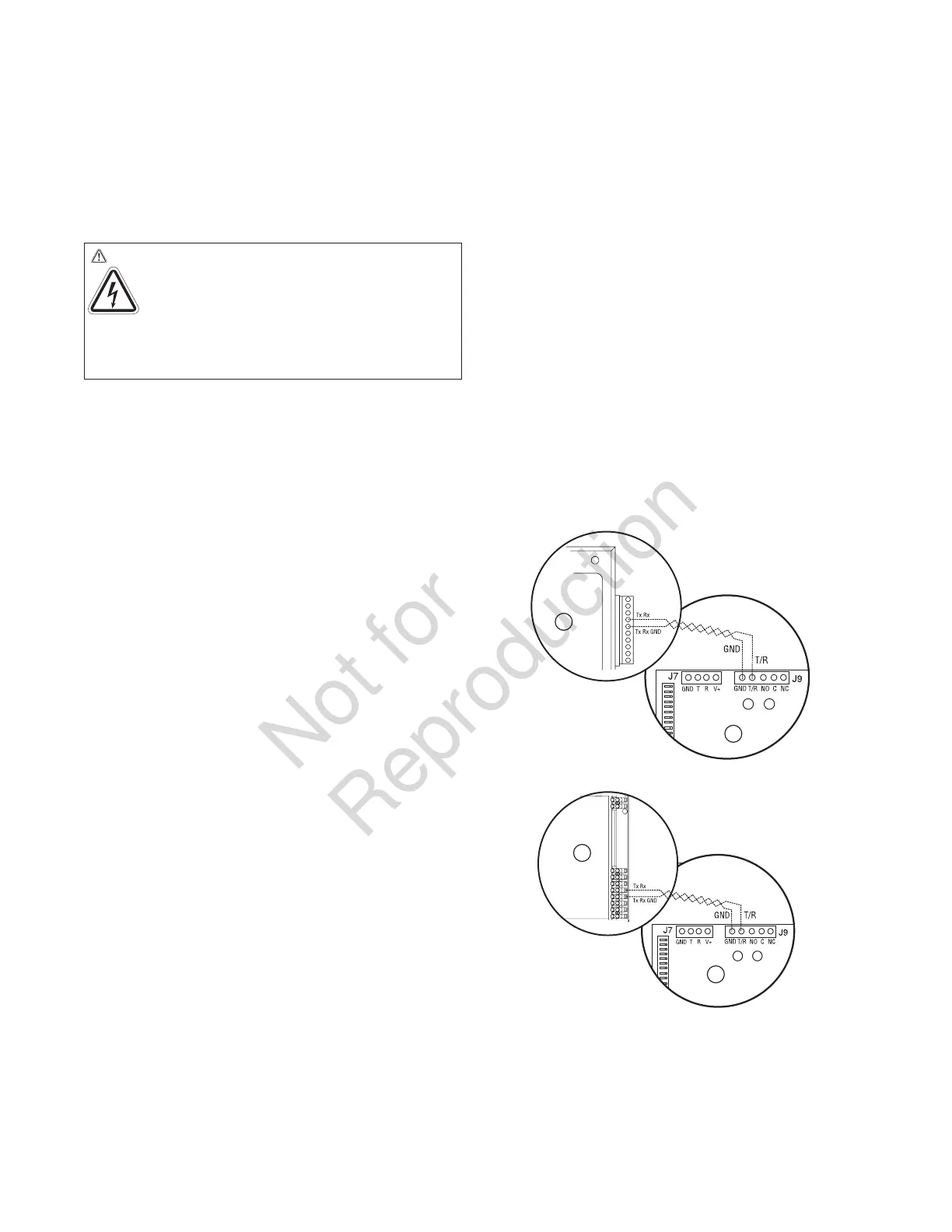
5. Using minimum #18 AWG twisted pair copper or
aluminum conductors, no greater than 200 ft. in length,
300 volt 75°C-90°C, connect “T/R” and “GND” terminals
on transfer switch control board (B) to the generator’s
control panel (A) “TxRx” and “TxRx GND” terminals via
ten pin connector or eight pin terminal. Count down to
the proper pin location on the generator control board
since visual alignment with its decal can be misleading:
6. Tighten all wire connections/fasteners to proper torque.
See label inside transfer switch enclosure or values
listed in remote module installation instructions for
proper torque values.
WARNING Shock Hazard. Hazardous voltage from
utility service or generator could cause death
or serious injury.
Remove all sources of
supply voltage and follow all disconnect
power instructions prior to performing any service
work. Verify with a meter that utility power has been
disconnected.
A
B
OR
A
B
 Loading...