Page 7 of 12
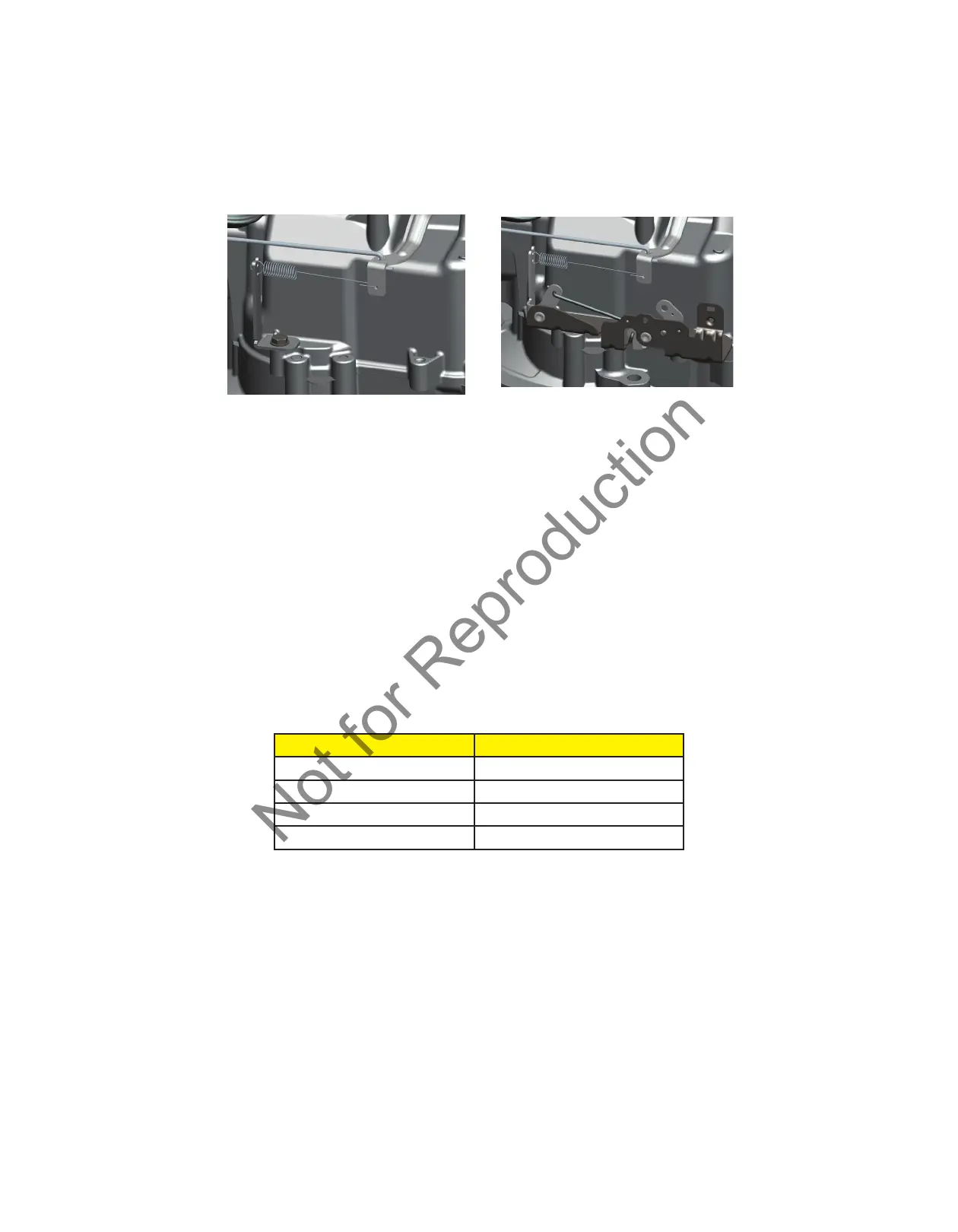
Control Bracket, Governor Lever, and Governor Spring
Either a fixed speed bracket with a single screw (Figure 8a) or a variable speed bracket with two screws (Figure 8b)
is installed.
Attach the governor spring first to the tab of the fixed or the variable speed bracket, then attach it to the governor
lever from the cylinder side, as shown (Figure 8a or 8b).
Figure 8a Figure 8b
Governor Adjustment Procedure
Static Adjustment
1. Loosen the governor nut.
2. Rotate the throttle linkage from idle to wide open throttle. Note the direction of rotation of the governor lever.
3. Rotate the governor shaft in the direction noted until it stops.
4. While holding the linkage and governor shaft, tighten the governor lever nut to the specification provided in this
APSI.
Dynamic Adjustment
1. Start the engine and allow it to warm up at idle for 3-5 minutes.
2. Move the throttle control (if equipped) to high speed. Using a tang bender, adjust the top no load speed by
bending the tang to obtain the equipment manufacturer’s top no load speed specification.
Spring Color Top No Load Speed
Blue 2600 - 2700
Purple 2800 - 3200
Orange 3200 - 3600
Yellow 3600 - 4000
3. Verify that all speeds meet specifications before returning the engine to service.
 Loading...