Page 8 of 12
Flywheel Brake and Stop Switch Wire
Position the flywheel brake on the cylinder mounting bosses behind the governor crank (Figure 9). Install the long
screw into the hole next to the brake pad. Install the short screw into the hole next to the stop switch. Tighten the
screws to the specification provided in this APSI.
Figure 9
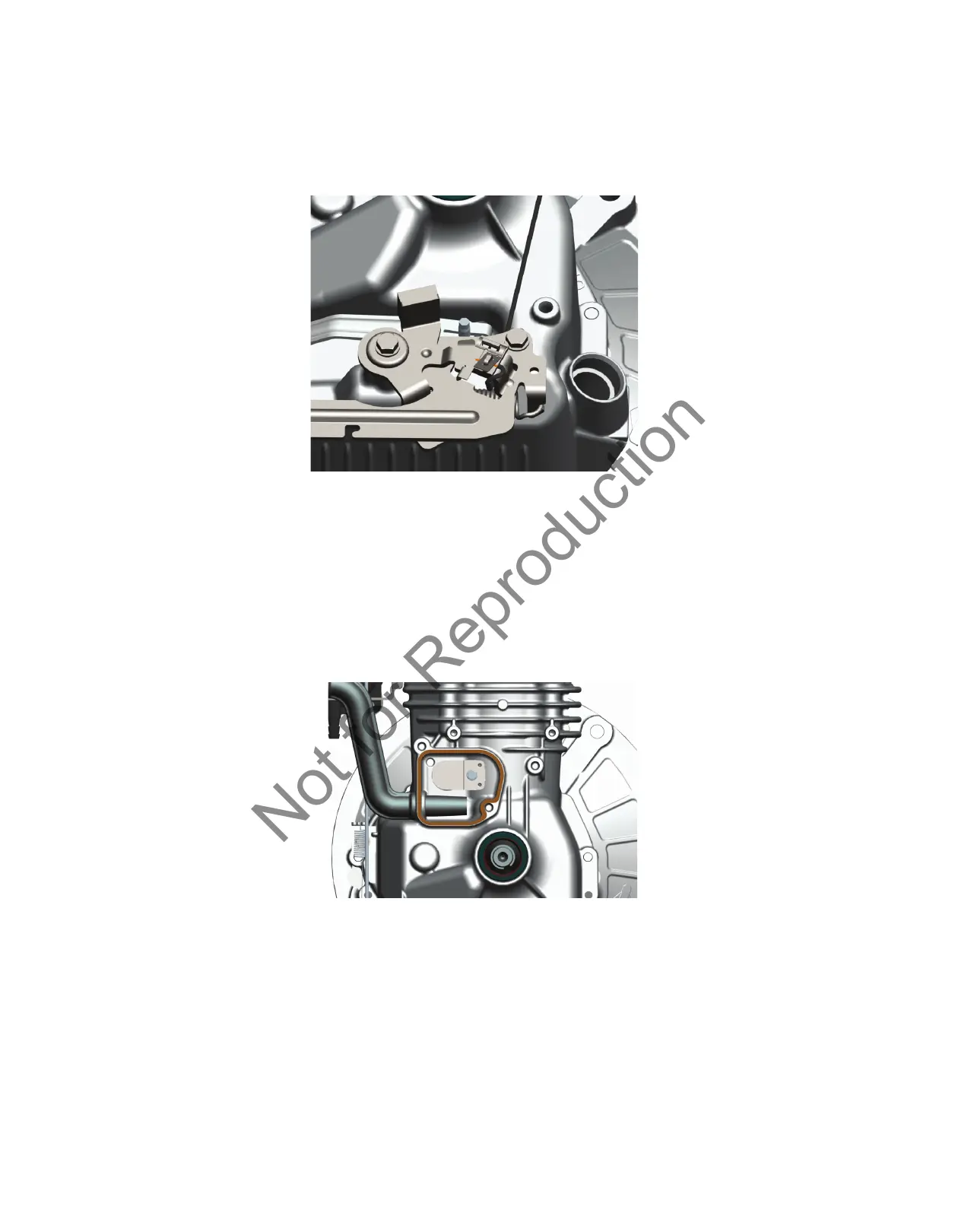
Flywheel Guard (Blower Scroll)
Ensure that the breather tube is fully installed at the back of the air cleaner base and against the cylinder casting
at the breather chamber. Apply a thin bead of sealant (p/n 100106) around the breather (Figure 10). Position the
flywheel guard on the cylinder and install the five screws. Tighten the screws to the specification provided in this
APSI.
Figure 10
 Loading...