Page 4 of 12
ASSEMBLY INFORMATION
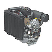
Piston Assembly and Orientation
The notch in the piston, the piston pin clip, and the MAG identification on the connecting rod all face the flywheel
side (mag side) of the engine (Figure 3). When installing replacement piston rings, the paint stripes on the rings
must be to the right side of the ring gaps.
Figure 3
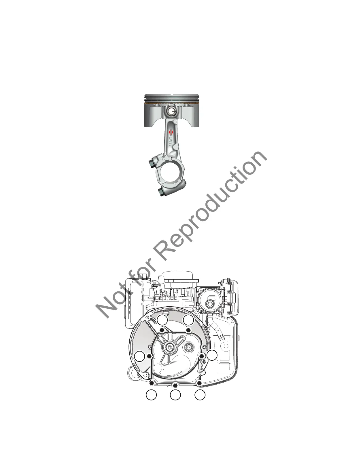
Sump and Seals
Install the sump bolts in positions 1 through 6 (Figure 4). Install the self-tapping sump screw in position 7. Do not
use the self-tapping screw in any other hole location. Using the sequence shown, tighten the bolts to the torque
specification provided in this APSI.
1
7
4
2
53
6
Figure 4
 Loading...