EasyManua.ls Logo

Briggs & Stratton E Series User Manual

Briggs & Stratton E Series
12 pages
To Next Page IconTo Next Page
Page #1 background imageLoading...
Page #1 background image
Rev.-
Page 1 of 12
85
JULY 2012
INTRODUCTION OF E SERIES™ ENGINES
09P600, 09P700 OHV VERTICAL SHAFT ENGINES
APSI #:
DATE:
SUBJECT:
MODELS:
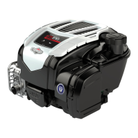
Briggs & Stratton has recently introduced the new E Series™ engine family, which includes the 550e Series™ and
550ex Series™ OHV engines.
This APSI provides basic servicing information in advance of the repair manual currently in development. System
tests and component removal/installation procedures are common with most other Briggs & Stratton engines. See
the Illustrated Parts List for service part numbers. The specifications, part numbers and/or procedures provided
here are PRELIMINARY and subject to change.
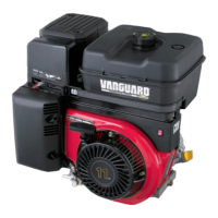
Figure 1
BRIGGS & STRATTON
Distribution Sales & Customer Support
ADVANCE PRODUCT SERVICE INFORMATION
Copyright© 2012 Briggs & Stratton Corporation
All language translations of this document are
derived from the original English source le.
Not for Reproduction
Question and Answer IconNeed help?

Do you have a question about the Briggs & Stratton E Series and is the answer not in the manual?

Briggs & Stratton E Series Specifications

General IconGeneral
BrandBriggs & Stratton
ModelE Series
CategoryEngine
LanguageEnglish

Summary

ENGINE DIMENSIONS

SERVICE NOTES

Flywheel

Instructions for flywheel removal and installation using specific tools.

Carburetor

Details on float bowl installation, screw threading, and needle valve seat removal.

Oil Capacity

Specifies reduced oil capacity (15 oz) and symptoms of overfilling.

Blower Housing Barcode Label

Procedure for transferring the barcode label to a new blower housing.

ASSEMBLY INFORMATION

Piston Assembly and Orientation

Instructions for piston orientation, pin clip, connecting rod, and piston ring installation.

Sump and Seals

Procedure for installing sump bolts and the self-tapping sump screw in sequence.

Cylinder Head

Carburetor and Air Cleaner Installation

Procedure for installing the carburetor spacer and mounting bracket on the cylinder head.

Primer and Air Cleaner Systems

Governor Adjustment Procedure

Static Adjustment

Procedure for adjusting the governor linkage and shaft while holding the nut.

Dynamic Adjustment

Procedure for adjusting top no-load speed using a tang bender, with speed chart.

Flywheel Brake and Stop Switch Wire

Flywheel Guard (Blower Scroll)

Fuel Tank and Fuel Hose

Oil Dipstick and Dipstick Tube

Rewind Starter and Blower Housing

ENGINE SPECIFICATIONS

Common Specifications

Table listing various engine parameters like bore, stroke, displacement, and oil capacity.

Common Service Parts

Fastener Torque Specification

SAE Torque Values

Torque values for fasteners in pound-inches and pound-feet.

Metric Torque Values

Torque values for fasteners in Newton-meters.

Component Dimensions

Cylinder and Cylinder Head Dimensions

Standard and reject dimensions for cylinder bore, head valve guides, and seats.

Crankshaft, Cam Shaft, and Connecting Rod Dimensions

Standard and reject dimensions for crankshaft journals, cam shaft journals, and connecting rod.

Piston and Piston Rings Dimensions

Standard and reject dimensions for piston pin diameter, bore, and piston ring end gap/clearance.

Related product manuals