23
WARNING
Generator voltage could cause electrical shock or
burn resulting in death or serious injury.
• Installation must be performed by a licensed
professional.
• Disconnect all sources of electricity before installing or
servicing equipment.
• Ground system before applying power.
WARNING
Battery electrolyte fluid contains acid and is extremely
caustic. Contact with battery contents could cause severe
chemical burns.
• DO NOT open or mutilate the battery
• Wear protective goggles, rubber apron, rubber boots
and rubber gloves.
• Immediately wash electrolyte from skin with water.
• If electrolyte contacts eyes, immediately flush with
water and seek medical attention.
• Spilled electrolyte is to be washed down with an acid
neutralizing agent.
The installer must supply and install a rechargeable 12 volt
starting battery. The starting battery MUST conform to the
specifications shown in this chart.
Battery Specifications
Specifications Standard Cold Start (Less than
30°F / -1°C)
Volts 12 Volt DC 12 Volt DC
Amps (Minimum) 540 CCA (Cold
Cranking Amps)
800 CCA(Cold
Cranking Amps)
Construction Wet Lead Acid Wet Lead Acid
Terminal Type Top Post Type Battery Top Post Type Battery
Dimensions (Maximum) BCI Size 26 or BCI Size
51
BCI Size 24
WARNING
With the battery connected, the generator may crank and
start without warning resulting in death or serious injury.
• Do not connect the negative (-) cable at the battery until
the installation is complete.
Install the battery as described inServicing the Batteryin
theMaintenancesection of this manual. Always make sure
that the NEGATIVE cable is connected last and that the red
POSITIVE terminal insulator is secure.
Use the supplied tie-down strap to secure the battery to the
unit. Each end of the strap should be attached to the existing
tabs in the base of the unit.
System Control Board
NOTICE Please see separate online manual:"Operation
InstructionsGC1031GENSET Controller" (part
number80086364)for details on set up and operation.
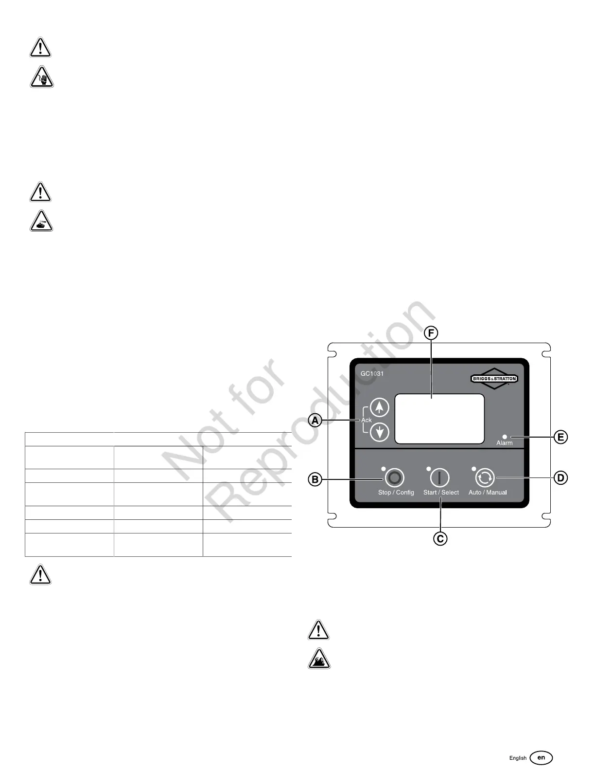
The generator control panel, located inside the generator
housing, is shown below.Brief descriptions of the controls
used during installation are:
(A) Menu / Programming Navigation Buttons
(B) Stop / Config Button
(C) Start / Select Button
(D) Auto / Manual Button
(E) Alarm
(F) Digital Display — Displays generator mode, menu options,
and alarms.
Detailed descriptions of the controls are located in
theDescription of Control Keyssection insidethe
online"Operation InstructionsGC1031GENSET
Controller"manual(part number80086364).
Initial Start-Up (No Load)
WARNING
Exhaust heat/gases could ignite combustibles
causing a fire, resulting in death or serious injury.
• Remove all combustible materials from in and around
the generator compartment.
The unit has been set-up for NG operation at the factory.
Fuel conversion, if needed, must be completed prior to

 Loading...