14
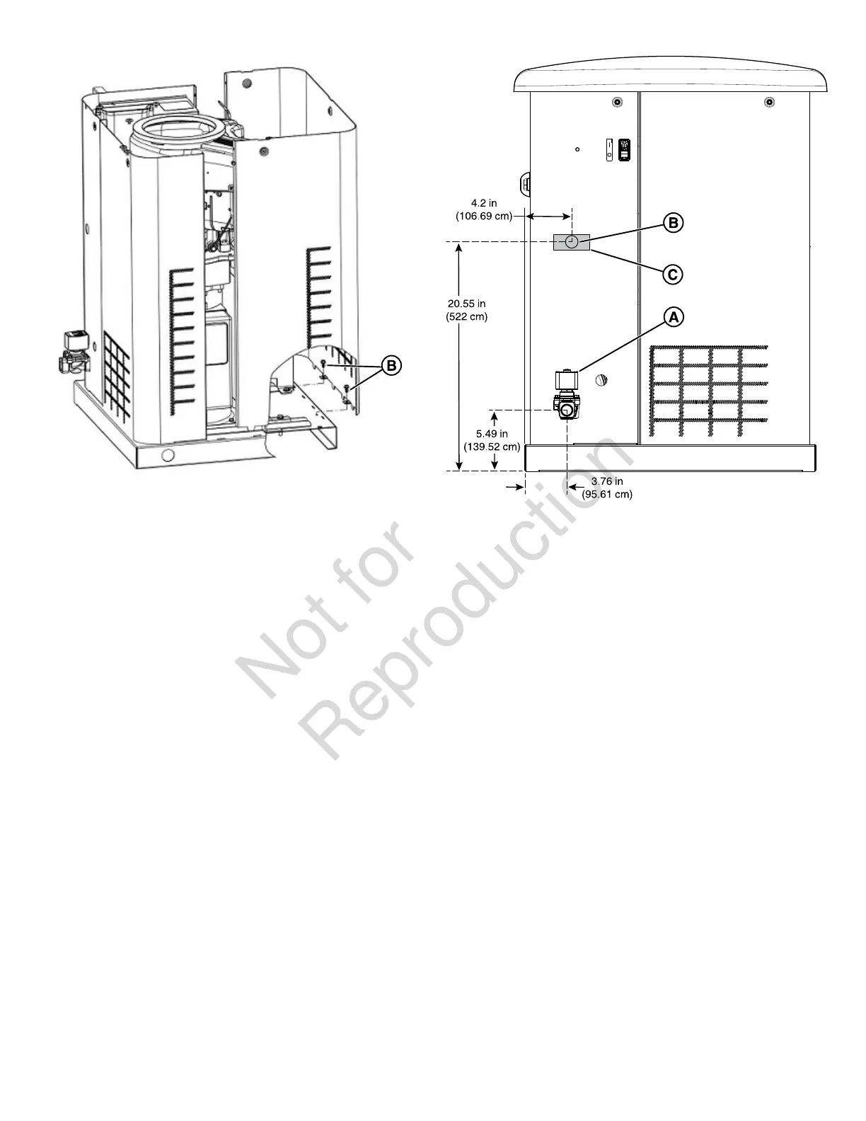
Electrical and Fuel Inlet Locations
The 3/4 inch N.P.T. fuel inlet connector (A) and electrical inlet
locations (B) are shown below.
A ½ inch knock-out is provided for the electrical inlet. This
inlet can be enlarged or supplemented to accommodate a
maximum conduit size of 1-½ inches. Make sure that the
installed conduit(s) enter the unit in zone (C) as shown in the
drawing that follows so that they correctly enter the electrical
box and do not interfere with the roof or any other component
of the generator.
Access Panels
The generator is equipped with an enclosure that has two
access panels, as shown in the image that follow.
Front Panel (A) and roof (B) are used to access:
• Battery Compartment
• Engine Oil Drain Hose
• Engine Oil Filter
• Engine Valve Cover
• Spark Plugs
Each generator is shipped with a set of identical keys
fastened to the fuel solenoid (C).

 Loading...