12
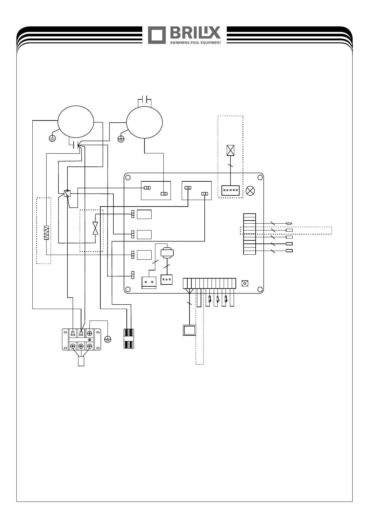
* The dotted line part are only used in some models
RUN/POW
2
2
2
2
2
3
Low Pressure switch
Water flow switch
5
Electronic Expansion Valve
Controller
High Pressure switch
Water out temperature
Water in temperature
Heating pipe temperature
Ambient temperature
Back temperature
Phase sequence protection
2
Transformer
2
FAN MOTOR
RED
ORG
C1
YLW/GRN
BLK
COMPRESSOR
YLW/GRN
S BLK
C2
R WHT
WHT
4-WAY
BLU
BRN
OUT1
OUT2
3
3
4
4
OUT3
OUT4
OUT5
AC-N
CN1
SW1
CN5
CN4
CN2
BRN
BLU
RED
BLU
C RED
BLU
RED
AC CONTACTOR
BRN
BLU
Remote controller
Base Electric Heater
YLW/GRN
220-240V ~ 50Hz
BLU
BRN
3-XPDLT0022S
PE
L
N
SWITCH
BRN
RED
(Water Pump)
Model: XHPFDPLUS160XHPFDPLUS140 &
Note: Electrical connection
The power supply for the heat pump must come, preferably, from an exclusive circuit with regulatory
protection components (30mA differential protection) and a magneto-thermal switch.
- The electrical installation must be carried out by a specialized professional (electrician) in accordance
with the standards and regulations in force in the country of installation.
- The heat pump circuit must be connected to a safety earth circuit at the terminal block.
11