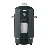
Step 9
Attach side table to left side of cart
frame assembly. Insert four
M6 X 12mm round head bolts
halfway into cart frame assembly.
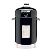
Step 10
Place table keyholes over bolts and
slide down, then tighten securely.
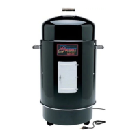
Step 11
Attach side burner to right side of
cart frame assembly. Insert four
M6 X 12mm round head bolts
halfway into cart frame assembly.
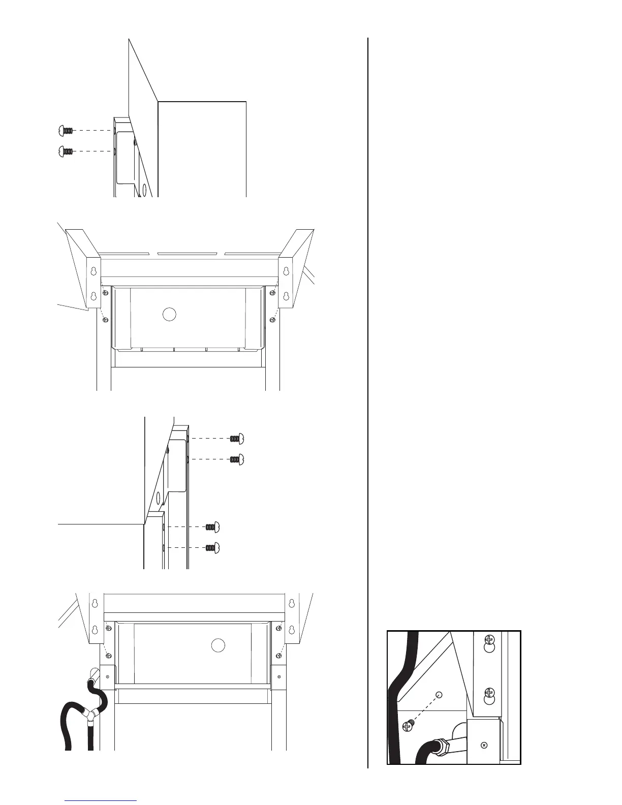
Step 12
Place side burner keyholes over
bolts and slide down, then tighten
securely. Fasten side burner front
panel to grill body with one
M6 X 12mm round head bolt.
27