28
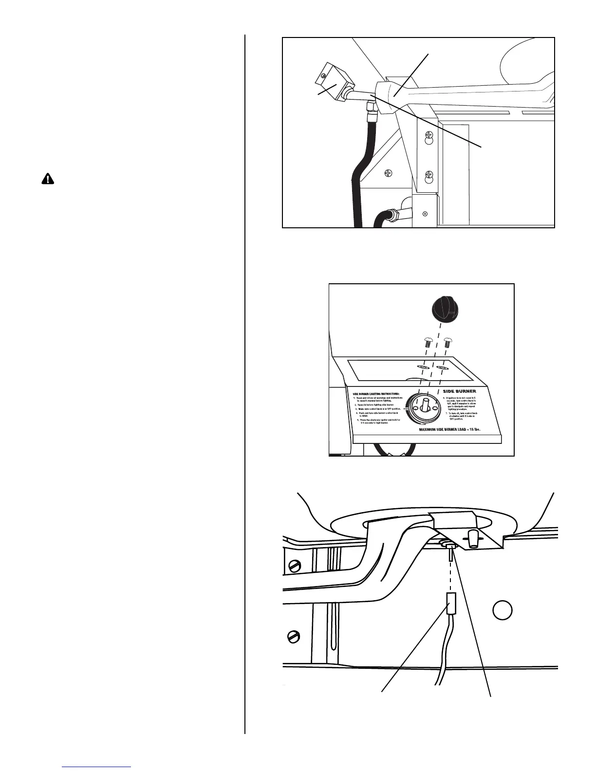
Step 13
Remove two M4 X 10mm bolts and
spring washers from the side
burner valve. Insert the side burner
valve stem through the hole in the
side burner table base, then firmly
seat the valve nozzle into the
burner venturi. Hold in place while
you perform Step 14.
Warning: Never use your grill
without leak testing all
gas connections and
hoses. See the section
on "Leak Testing" in this
manual for proper
procedures.
Step 14
Place the bezel over the valve stem
and position over holes in side
burner base and side burner valve
assembly. Attach with two
M4 X 10mm bolts with spring
washers which come with valve.
Then install the side burner control
knob onto valve stem.
Step 15
Attach side burner igniter lead to
the electrode as illustrated.
Side
Burner
Valve
Burner Venturi
Valve
Nozzle
Side Burner Igniter
Lead
Electrode